User’s Manual UDP6900 Series Digital Control Power Supply
Instruments.uni-trend.com 28 / 44
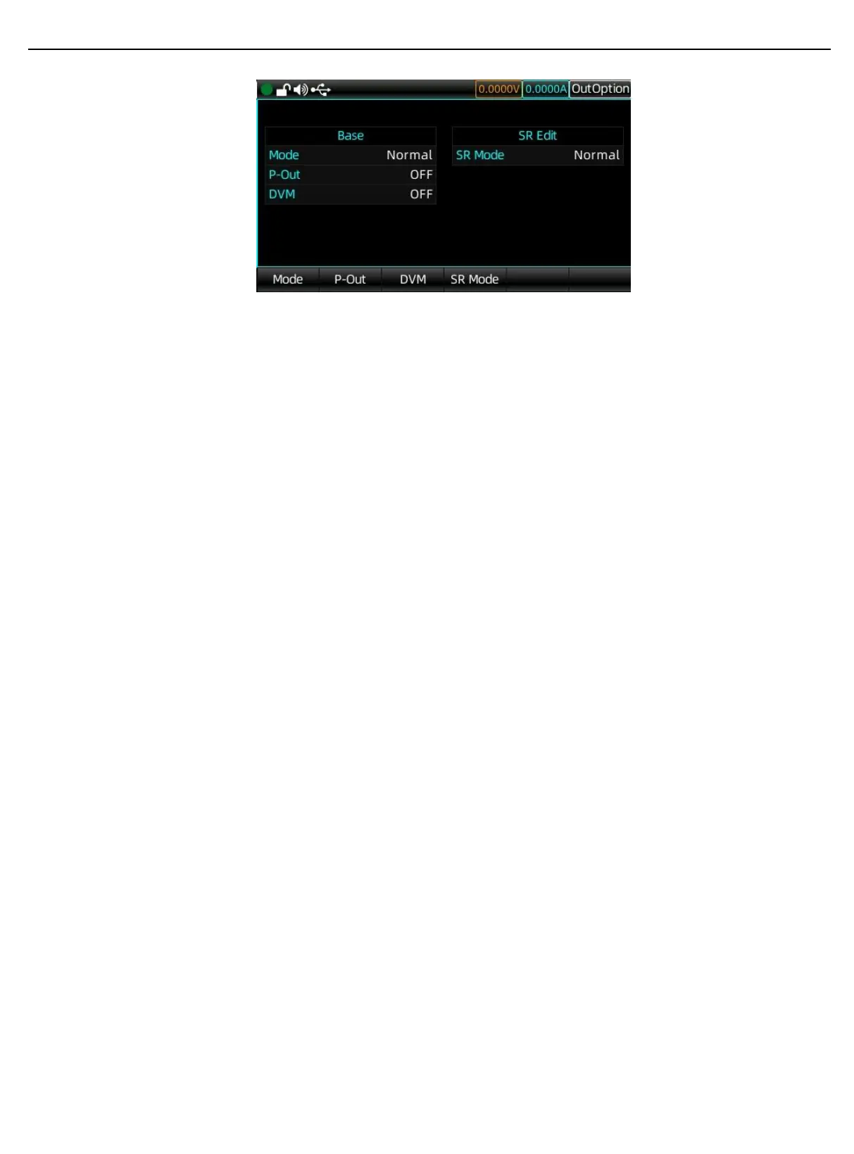
Output Settings Interface
Operation Steps
1. Press the power switch to power up the instrument, press the Menu key to enter the menu page,
and press Output Settings or rotate the encoder knob to select Output Settings and push the
encoder knob to enter the output setting page.
2. Press the Slope Mode button to switch to normal, CV slope or CC slope.
3. Press the Slope Setting button to select the slope in different mode.
4. Normal mode: the slope parameter cannot be set.
5. CV slope mode: set the rising and falling slope of voltage.
6. CC slope mode: set the rising and falling slope of current.
7. The slope parameter can be set by the encoder knob and the numerical keyboard.
UDP6900 series provides three power operation modes.
Normal mode: the output voltage and current is set by manual or remote command.
External analog control (Ext-V): the voltage and current setting values change according to the voltage values
Vs and Is input from the rear interface.
External digital control (Ext-D): the voltage, current, OVP and OCP are automatically loaded into the
corresponding preset parameters 0~7 based on the external digital inputs D0, D1 and D2, which form the
digital quantity 0~7. Please refer to section 3.15.3 for parameter explanation.
Operation Steps of Power Mode
1. Press the power switch to power up the instrument, and press the Menu key to enter the menu
page, and then press Output Settings button or rotate the encoder knob to select the Output
Settings and push the encoder knob to enter the output settings page.
2. Click on the Operating Mode button, and rotate the encoder knob and push the encoder knob
multiple times to switch to different operating mode.
3.12.3 System Settings
System settings include backlight, sound, RS232, network and communication settings. You can also check
the information of this machine.