EasyManuals Logo
Home>UNI-T>Multimeter>UT202A

UNI-T UT202A User Manual

UNI-T UT202A
25 pages
To Next Page IconTo Next Page
To Previous Page IconTo Previous Page
Page #14 background imageLoading...
Page #14 background image
1413
UT202A Operating Manual
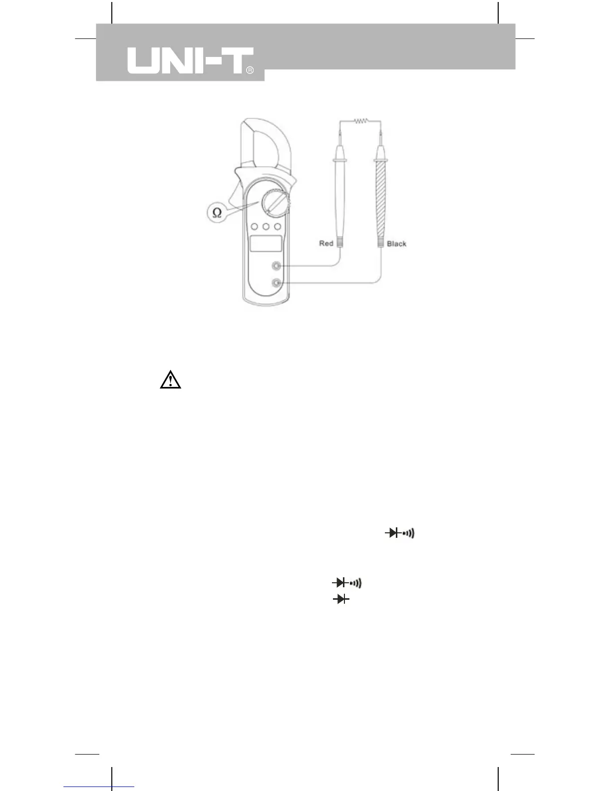
D. Testing Diodes (see gure 6)
Warning
To avoid damages to the Meter or to the
devices under test, disconnect circuit power and
discharge all the high-voltage capacitors before
testing diodes.
To test the diode out of a circuit, connect the
Meter as follows:
1. Insert the red test lead into the
terminal and the black test lead into the
COM terminal.
2. Set the rotary switch to and press
SELECT button to select measurement
mode.
3. For forward voltage drop readings on any
semiconductor component, place the red
test lead on the component’s anode and
place the black test lead on the component’s
cathode.
Ω
(gure 5)

Questions and Answers:

Question and Answer IconNeed help?

Do you have a question about the UNI-T UT202A and is the answer not in the manual?

UNI-T UT202A Specifications

General IconGeneral
AC voltage600 V
Resistance (max)0.02 Ω
Measuring categoryCAT II 600V, CAT III 300V
Battery voltage9 V
Test leadsYes
CertificationCE, RoHS
Product colorBlack, Red
Weight and Dimensions IconWeight and Dimensions
Depth30 mm
Width75.6 mm
Height210 mm
Weight220 g

Related product manuals