1615
UT202A Operating Manual
Note:
● To remove the objects being tested from
the circuit when measuring can obtain a more
accurate result.
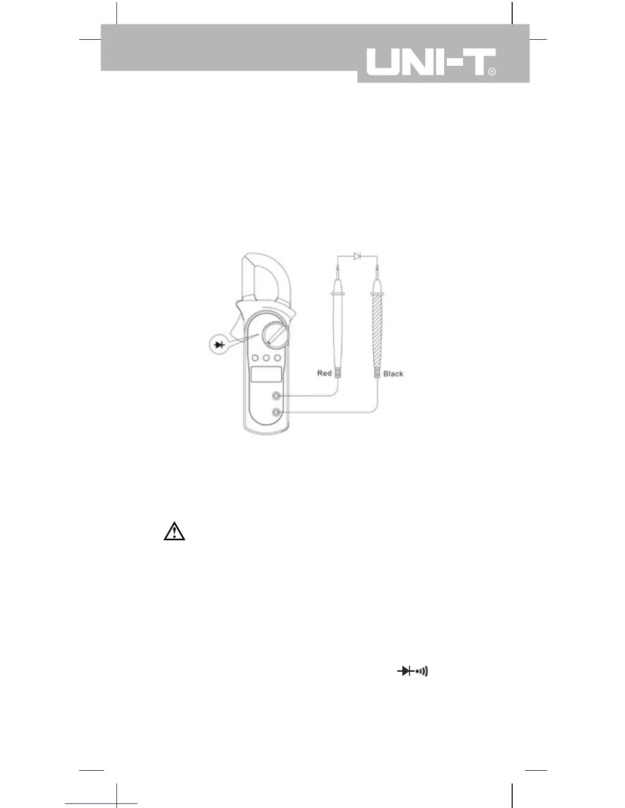
● When diode testing has been completed,
disconnect the connection between the testing
leads and the circuit under test and remove
testing leads from the input terminals.
E. Testing for Continuity (see gure 7)
Warning
To avoid damages to the Meter or to the
devices under test, disconnect circuit power and
discharge all the high-voltage capacitors before
measuring continuity.
To test for continuity, connect the Meter as
follows:
1. Insert the red test lead into the
terminal and the black test lead into the
COM terminal.
VΩ
(gure 6)
 Loading...