G.Make Measurements(8)
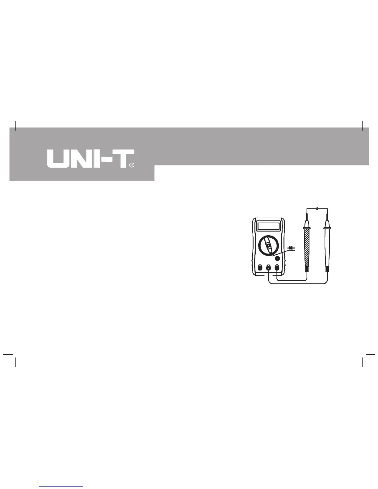
6. Diode measurement (see figure 7)
(figure 7)
1) Avoid damages to the meter. When
measuring diode, cut off the power supply
of the object and make sure there is no
charge in capacitor.
2) When measuring voltage drop of diode,
transistor, and other semiconductor
component at diode function, its silicon
semiconductor structure should be normal
positive reading and stay between 0.5V
and 0.8V. Negative display being “1” means
open circuit; when the red test lead is
positive pole and the black one is negative pole.
24
Model UT30B/C/D/F: OPERATING MANUAL
 Loading...