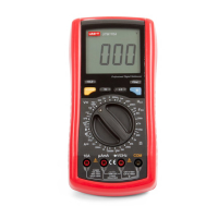
(figure 6)
Measurement Operation (4)
D. Measuring Continuity, Resistance,
Conductance & Capacitance
Warning
To avoid damages to the Meter or to the devices
under test, disconnect circuit power and discharge
all the high-voltage capacitors before measuring
continuity, resistance, conductance and capacitance.
When measuring capacitance, use the DC Voltage
function to confirm that the capacitor is discharged.
Never attempt to input over 60V in DC or 30V rms in
AC to avoid personal dangerous.
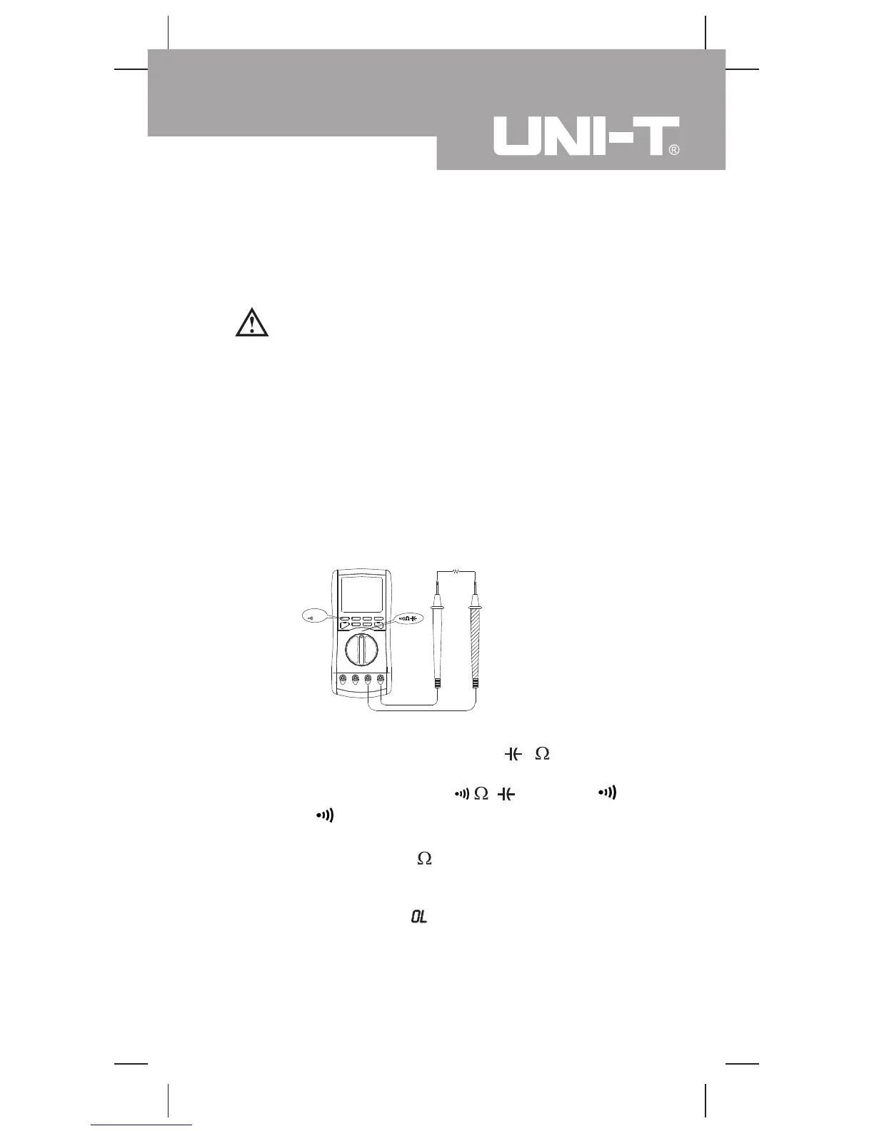
Testing for Continuity (see figure 6)
To test for continuity, connect the Meter as below:
1. Insert the red test lead into the
V Hz terminal
and the black test lead into the COM terminal.
2. Set the rotary switch to
and press to
select
measurement mode.
3. The buzzer sounds if the resistance of a circuit under
test is less than 100 .
Note
l The LCD displays
indicating the circuit being
tested is open.
l When continuity testing has been completed,
disconnect the connection between the testing leads
and the circuit under test.
Select
Test
blackred
Model UT70C: OPERATING MANUAL
19
 Loading...