24
To test for continuity, connect the Meter as below:
1. Insert the red test lead into the VΩ terminal and
the black test lead into the COM terminal.
2. Set the rotary switch to .
3. Connect the test leads across with the object being
measured.
The buzzer does not sound when the resistance
value is >100Ω. The circuit is disconnected.
The buzzer sounds continuously when the resistance
value is 10Ω. The circuit is in good condition.
Note
l The LCD displays 1 indicating the circuit being tested
is open.
l Open-circuit voltage is approx. 3V.
l When continuity testing has been completed,
disconnect the connection between the testing leads
and the circuit under test.
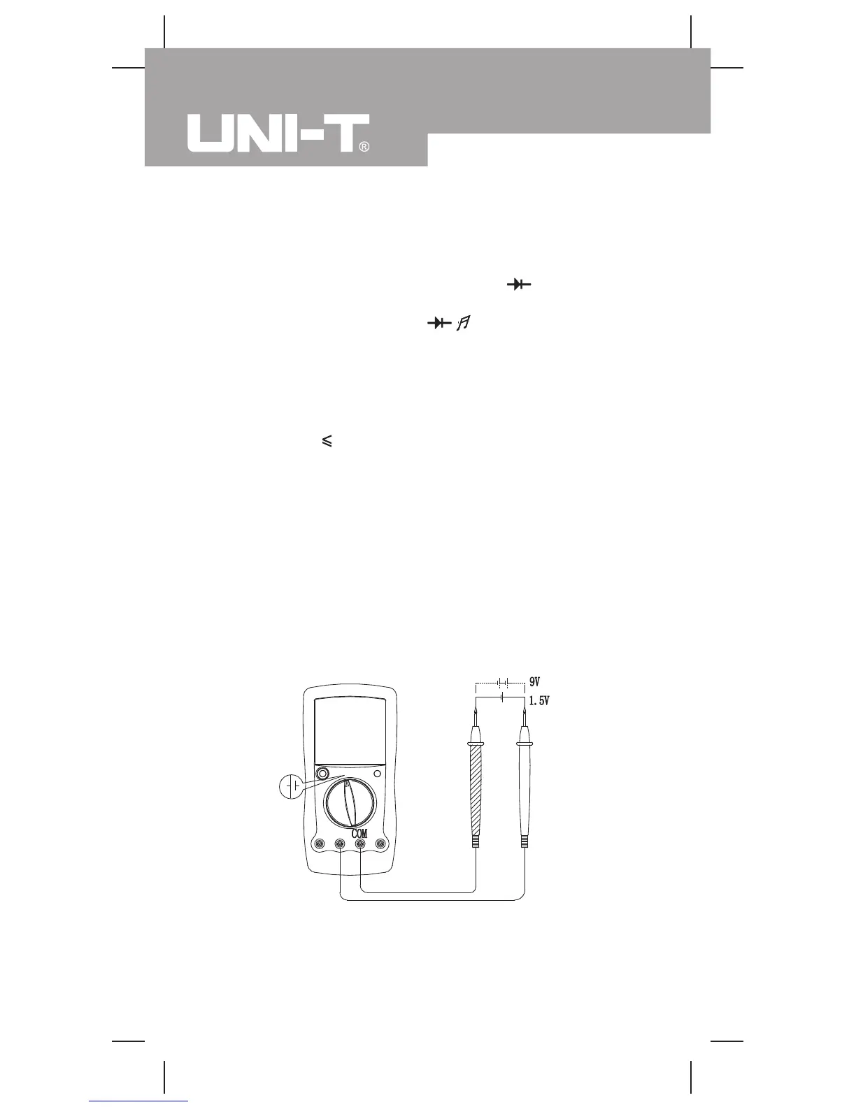
G.Battery Test (see figure 8)
Measurement Operation(11)
( figure 8)
black red
Model UT90A: OPERATING MANUAL
 Loading...