UTD2000 Series User Manual
29
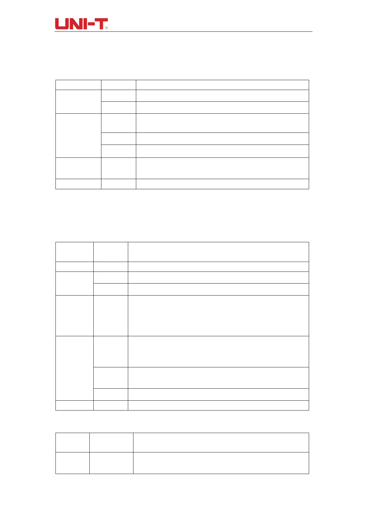
Table 4-3 Pulse width setting menu
Set the positive pulse width as trigger signal
Set the negative pulse width as trigger signal
Trigger when pulse width is greater than the set value
Trigger when pulse width is less than the set value
Trigger when pulse width is in the range of set value.
The pulse width is set at 20ns~10s, adjust the time through multifunctional
knob on the front panel.
4.3 Slope trigger
After the slope trigger is selected, DSO generates a trigger when the rising/descending
slope of signal.
Table 4-4 Slope trigger menu
Set CH1 as trigger signal.
Set CH2 as trigger signal.
Block the DC components of insput signals.
Hold off the high-frequency components (over 80kHz) of the signal.
Hold off the high-frequency noise of the signal to reduce the probability of mis-
trigger.
When there is no signal input, the system will automatically collect waveform data
and the scan base line will be displayed on the screen. When there is signal input,
the system will automatically switch to trigger scan.
Stop collecting data when there is no trigger signal, the system will conduct
trigger scan when the trigger signal generates.
The DSO will only perform 1 cycle of triggering when there is triggering signal.
Table 4-5 Slope setting menu
The DSO generates a trigger when the slew rate of rising edge of signal is
higher than the specified slew rate.

 Loading...

