UTD2000 Series User Manual
31
Applicable NTSC video signal.
Set the video line to synchronous triggering.
Set the video to sync and trigger on specific line, adjust through the
multifunctional knob on front panel.
Set the video to sync and trigger on odd field.
Set the video to sync and trigger on even field.
Adjust through the multifunctional knob on front panel.
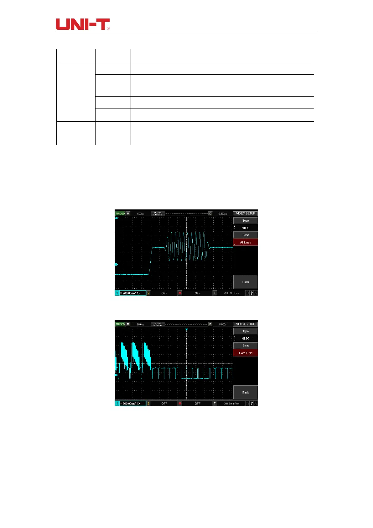
Figure 4-1 is an example screen display when PAL video trigger model is selected as
standard and the synchronization mode is selected as line synchronization. Figure 4-2 is
an example screen display when the synchronization mode is set to field synchronization.
Figure 4-1 Video Trigger: Line Synchronization
Figure 4-2 Video Trigger: Field Synchronization
4.5 Alternating trigger
During alternating trigger, the trigger signal comes from two vertical channels. Alternating
trigger is useful for observing two signals with different frequency. See the figure below for
display of triggered alternating waveform example and Table 4-7 for triggered alternating
menu setting.

 Loading...

