UTD2000 Series User Manual
32
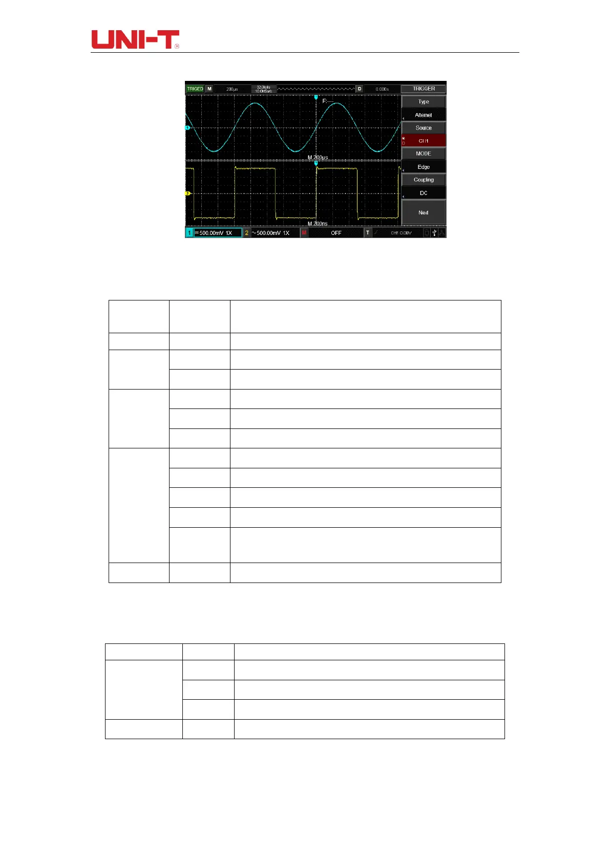
Figure 4-3 Observing Signals with Two Different Frequencies by
Alternating Trigger Mode
Table 4-7 Alternating Trigger Menu (Page 1)
Table 4-8 Alternating Trigger Menu (Page 2)
Select CH1 as current channel
Select CH2 as current channel
Set the edge as trigger mode
Set the pulse width as trigger mode
Set the slope as trigger mode
Pass through DC and AC components of triggering signal.
Block the DC component of triggering signal.
Reject high-frequency component of the triggering signal.
Reject low-frequency component of the triggering signal.
Suppresses high frequency noise in the signal and reduces the
probability of the oscilloscope being falsely triggered .
Set trigger on the signal rising edge.
Set trigger on the signal falling edge.
Set trigger on the signal both rising and falling edge.

 Loading...

