- 3 -
3. ELECTRIC CONNECTION
- .None of the switches must be in ON position.
- Make sure that the voltage, frequency and power values marked on the descriptive plate of the machine are
in conformity with the electric network mains.
- Mount a plug on the end of the machine cable (plug with grounding: green/yellow wire).
. POWER CONNECTIONS
Set the machine switch to Position
.
The machine is delivered with a cable consisting of 5 numbered wires.
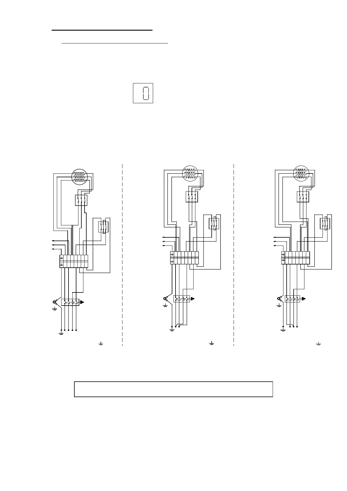
Make sure that the machine connection matches the available voltage network (see wiring
diagrams hereunder). Bring the necessary modifications into the supply cable and the plug located
near the electrically-driven pressurestat.
WIRING DIAGRAMS
N1 L1 L2 L3
N0 1 2 3
MAIN
COMMUTATOR
BORNIER
TERMINAL PLUG
PRESSOSTAT
PRESSURESTAT
RESISTANCE
HEATING ELEMENT
1
4
2
6
3
5
4 5 6
THERMOSTAT
SECURITE RESISTANCE
HEATING ELEMENT
SAFETY THERMOSTAT
1
5
6
1 2 3
P1 P2 P3
CABLE
CORD
N
2 3
4
ALIMENTATION BOITIERS ELECTRONIQUES
ET TRANSFORMATEUR NEON
FEEDING ELECTRONIC BOXES
AND NEON TRANSFORMER
BORNIER
TERMINAL PLUG
PRESSOSTAT
PRESSURESTAT
RESISTANCE
HEATING ELEMENT
THERMOS TAT
SECURITE RESISTANCE
HEATING ELEMENT
SAFETY THERMOSTAT
CABLE
CORD
ALIMENTATION BOITIERS ELECTRONIQUES
ET TRANSFORMATEUR NEON
FEEDING ELECTRONIC BOXES
AND NEON TRANSFORMER
MAIN
COMMUTATOR
BORNIER
TERMINAL PLUG
PRESSOSTAT
PRESSURESTAT
RESISTANCE
HEATING ELEMENT
THERMOSTAT
SECURITE RESISTANCE
HEATING ELEMENT
SAFETY THERMOSTAT
CABLE
CORD
ALIMENTATION BOITIERS ELECTRONIQUES
ET TRANSFORMATEUR NEON
FEEDING ELECTRONIC BOXES
AND NEON TRANSFORMER
N Ph
Ph1 Ph2 Ph3
N Ph1 Ph2 Ph3
380 / 400 / 415V TRI + N +
200 / 230 / 240 V MONO +
200 / 230 / 240V TRI +
4 5 6
NL1PEL3 L2
N 1 2 3
1
4
2
6
3
5
4 5 6
1 2 3
P1 P2 P3
4 5 6
N 1 2 3
N1 L1 L2 L3
N0 1 2 3
1
4
2
6
3
5
4 5 6
1 2 3
P1 P2 P3
4 5 6
N 1 2 3
N 1 2 3
N 1 2 3
N1 L1 L2 L3
N0 1 2 3
MAIN
COMMUTATOR
N 1 2 3
1
5
6
4
2
3
NL1
PE L3 L2
1
2
5
6
3
4
N
NL1PEL3 L2
A : Electronic box
B : Switch
IN ALL CASES, THE GREEN/YELLOW WIRE
MUST BE EARTHED
 Loading...