27
Adjustment info
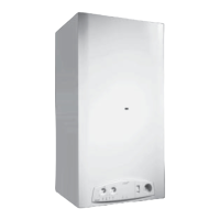
fig. 32
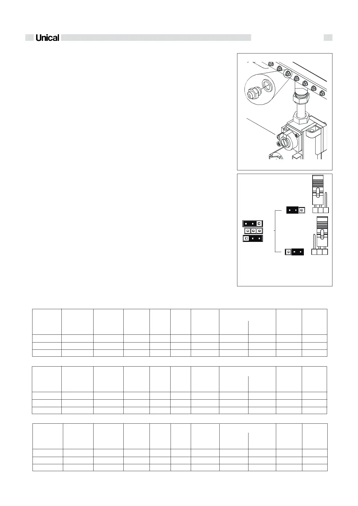
fig. 33
LPG
JP1
NA T
LPG
NA T
1
IVEN 04 CTN 24 F - IVEN 04 RTN 24
Gas
consump-
tion
max.
Natural gas
Propan
Butan
10,07 - 23,88
10,07 - 23,88
10,07 - 23,88
11,5 - 26,5
11,5 - 26,5
11,5 - 26,5
20
37
28-30
14
14
14
-
-
-
IVEN 04 CTFS 24 F - IVEN 04 RTFS 24
9,95 - 23,94
9,95 - 23,94
9,95 - 23,94
11,5 - 26,5
11,5 - 26,5
11,5 - 26,5
20
37
28-30
14
14
14
-
-
-
IVEN 04 CTFS 28 F - IVEN 04 RTFS 28
9,8 - 27,45
9,8 - 27,45
9,8 - 27,45
11,5 - 30,5
11,5 - 30,5
11,5 - 30,5
20
37
28-30
14
14
14
-
-
-
Natural gas
Propan
Butan
Natural gas
Propan
Butan
1,25
0,75
0,75
2,1
6,4
4,6
11,0
32,1
25,8
1,22 m³/h
0,89 kg/h
0,91 kg/h
2,80 m³/h
2,06 kg/h
2,09 kg/h
1,25
0,75
0,75
2,0
6,2
4,8
10,8
35,3
27,1
1,22 m³/h
0,89 kg/h
0,91 kg/h
2,80 m³/h
2,06 kg/h
2,09 kg/h
1,25
0,78
0,78
2,1
4,4
3,7
13,8
35,5
27,4
1,23 m³/h
0,89 kg/h
0,91 kg/h
3,24 m³/h
2,37 kg/h
2,40 kg/h
JP1: For nat. gas boilers, the jumper is
on NAT.
For LPG boilers, the jumper is on
LPG.
2.7 - MODIFICATION FOR
OTHER GASES
The boilers are manufactured for the type of
gas specifically required upon order.
Any subsequent conversion must be perfor-
med by qualified technicians who will use the
kits supplied by Unical and perform the con-
version and required adjustments for correct
preparation of the boiler for use.
To convert the boiler from one type of gas to
another proceed as follows:
for conversion from natural gas to LPG
- remove the main burner;
- disassemble injectors “1” (fig. 32) of the
main burner and replace them with those
with a diameter corresponding to the new
type of gas (see table “INJECTORS -
PRESSURES”);
- reassemble the main burner;
- position the jumper on the modulation PCB
in the panel board as shown in fig. 33
- remove plug ‘’A’’ (fig.28) on the gas valve
and fully tighten max pressure adjustment
screws ‘’B’’ (fig.29)
- check the pressure value upstream the gas
valve (see table “INJECTORS - PRESSU-
RES”) and adjust the pressure of the bur-
ner as indicated in section “ADJUSTING
THE BURNER”
- check that the burner is functioning pro-
perly;
- check that there are no gas leaks.
- tighten the plug ”A” (fig.28) of the max
pressure adjustment screw
- when the conversion is completed, fill in
label supplied with the kit with the informa-
tion required and stick it onto the boiler
alongside the data plate.
for conversion from LPG to natural gas
- remove the main burner;
- disassemble injectors “1” (fig. 32) of the
main burner and replace them with those
with a diameter corresponding to the new
type of gas (see table “INJECTORS -
PRESSURES”);
- reassemble the main burner;
- position the jumper on the modulation PCB
in the panel board as shown in figure 33;
- remove plug ‘’A’’ (fig.28) on the gas valve
- check the pressure value upstream the gas
valve (see table “INJECTORS - PRESSU-
RES”) and adjust the burber pressure as
indicated in section “ADJUSTING THE
BURNER”;
- check that the burner is functioning pro-
perly;
- check that there are no gas leaks.
- tighten the plug “A” (fig.28) of the max
pressure adjustment screw;
- when the conversion is completed, fill in
label supplied with the kit with the informa-
tion required and stick it onto the boiler
alongside the data plate.
Nominal
Output
(kW)
Nominal
input
(kW)
Supply
pressure
(mbar)
Ø
Diaphragme
(mm)
min.
(mbar)
max
(mbar)
Ø
Nozzles
(mm)
Gas
consump-
tion
min.
The pressures at the burner indicated in the following table must be checked after the boiler has been operating for 3 minutes.
TABLE NOZZLES - PRESSION - DIAPHRAGME - CONSUMPTION
Tipe of
gas
No. of
Nozzles
Burner pressure
Gas
consump-
tion
max.
Nominal
Output
(kW)
Nominal
input
(kW)
Supply
pressure
(mbar)
Ø
Diaphragme
(mm)
min.
(mbar)
max
(mbar)
Ø
Nozzles
(mm)
Gas
consump-
tion
min.
Tipe of
gas
No. of
Nozzles
Burner pressure
Gas
consump-
tion
max.
Nominal
Output
(kW)
Nominal
input
(kW)
Supply
pressure
(mbar)
Ø
Diaphragme
(mm)
min.
(mbar)
max
(mbar)
Ø
Nozzles
(mm)
Gas
consump-
tion
min.
Tipe of
gas
No. of
Nozzles
Burner pressure
 Loading...