6
Installation info
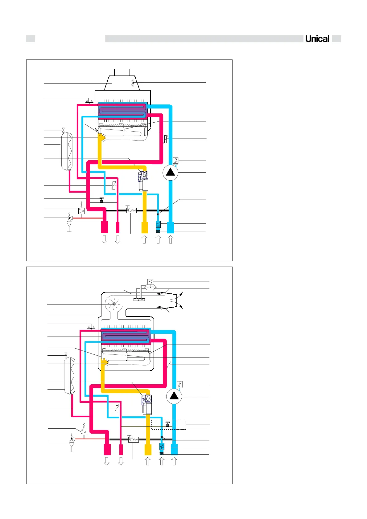
1.3 - HYDRAULIC CIRCUIT
fig. 3
IVEN 04 CTN 24 F
IVEN 04 CTFS 24 F - IVEN 04 CTFS 28 F
fig. 2
12
13
5
6
8
9
10
14
15
17
4
7
19
18
20
3
1
2
21
9
11
16
RF
GMC
R
F
G
M
C
3
19
4
7
6
8
9
13
14
15
18
16
17
5
20
22
23
12
11
21
24
8
1
2
10
1 Heating circuit safety valve
2 Minimum water pressure switch
3 Filling valve (except French, Belgium
and England version)
4 D.H.W. temperature sensor
5 Gas valve
6 Expansion vessel
7 Burner nozzles
8 Expansion vessel filling valve
9 Ignition electrode
10 Bithermal heat exchanger
11 H.L. thermostat
12 Flue gas manifold/down-draught
dverter
13 Flue gas anti-spillage thermostat
14 Ionisation electrode
15 C.H. temperature sensor
16 Automatic air vent
17 Circulating pump
18 D.H.W. flow restrictor 10-12 l/min
19 Flow switch
20 Cold water filter
21 By-pass
M C.H. system flow
C D.H.W. outlet
G Gas inlet
F D.C.W. inlet
R C.H. system return
1 Heating circuit safety valve
2 Minimum water pressure switch
3 D.H.W. temperature sensor
4 Expansion vessel
5 Gas valve
6 Burner nozzles
7 Expansion vessel filling valve
8 Ignition electrode
9 Bithermal heat exchanger
10 H.L. thermostat
11 Room sealed combustion chamber
12 Flue gas extractor fan
13 Air/flue coaxial duct
14 Micro-switch on flue gas pressure
switch
15 Flue gas pressure switch
16 Ionisation electrode
17 Heating temperature sensor
18 Automatic air vent
19 Circulating pump
20 Filling valve (except French, Belgium
and England version)
21 D.H.W. flow restrictor 10-12 l/min
22 D.H.W. Flow switch
23 Cold water filter
24 By-pass
M C.H. system flow
C D.H.W. outlet
G Gas inlet
F D.C.W. inlet
R C.H. system return

 Loading...