6509
TABLE OF CONTENTS
DESCRIPTION PAGE
Table of Contents ............................................................................ ....................... ............ 1
List of Illustrations ............................................................................. .....................……… 1
Introduction ....................................................................................... .....................……… 3
Installation Instruction ....................................................................... .....................……… 3
Operating Instructions ........................................................................ .....................……... 4
Safety Warnings ................................................................................. .....................……… 4
Sharpening Instructions ...................................................................... .....................…….. 5 - 6
Operator's Care of Slicer - Cleaning Instructions ................................... .....................…... 6
Mechanic's Maintenance ...................................................................... .....................……. 8-9
Lubrication Instructions ...................................................................... .....................…….. 9
Trouble Shooting Guide ...................................................................... .....................…….. 10
Repair Instructions including Disassembly, Replacement, and Reassembly....................... 11 - 13
Replacement Parts Lists Keyed to Figure Drawings ................................ .....................…. 14-22
Wiring Diagram ................................................................................. .....................……… 23 - 25
Warranty Information ..............................................................................................…….... Back Cover
LIST OF ILLUSTRATIONS AND FIGURE DRAWINGS
ILLUSTRATIONS PAGE
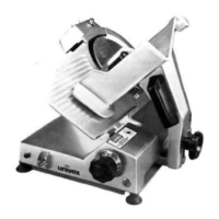
Fig. 1 Overall View of Slicer Model 6509................................................................……... 2
Fig. 2 Lubrication Diagram and Instruction ..............................................................……... 9
Fig. 3 Sharpener, Knife, Pulley, and Motor Assemblies ............................................…….. 14 - 16
Fence, Fence Adjustment, Carriage, Carriage Arm, Carriage Arm Support, and Feed
Fig. 4A Capacitor Panel 220-240V .............................................................................……… 20
Fig. 4B Capacitor Panel 100 V ...................................................................................………. 21
Fig. 5 Base and Slice Adjustment Knob Assembly .....................................................……. 22
Fig. 6 Wiring Diagram 115V, 50/60HZ, 1PH ............................................................…….. 23
Fig 6A Wiring Diagram 220-240V, 50/60HZ, 1PH ......................................................……. 24
Fog. 6B Wiring Diagram 100V. 50/60HZ. 1PH ............................................................…….. 25
PAGE 1
 Loading...