DS1033-137C 31
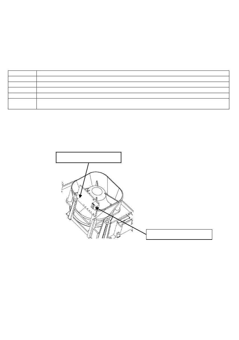
5.2 CONNECTIONS
Supply the card by connecting the red wire to the “+B” terminal, the black wire to the “-“ terminal (the white
wire will remain free; isolate it to prevent it touching electrically live parts;
Connect the protection module output (Tamper Contact) in series with the anti-opening microswitch,
or with a 24h-type input in the main control unit;
The two wires with Faston connectors (blue and yellow-green) are not used in this siren model; leave them
coiled up so that they do not touch each other or other electrical parts;
Close and secure with suitable screws the internal protecting cage.
Data line wire for siren module (not used)
Connecting wire to external cover (not used)
Connecting wire to internal cage (not used)
Sabotage contact (to be serially connected to tamper-preventing micro-switch or to a 24h
central unit input)
FUNCTIONAL CHECK
By obscuring with a hand the TX and RX module elements or by short-circuiting for an instant the two
fastons (blue wire and yellow-green wire), the green LED intensity will increase for a few instants, in order
to then go back to its initial status.
NOTE: Memory deletion occurs with the following S (system activation).
Close and secure the external cover with suitable screw.
Module inserting direction
 Loading...