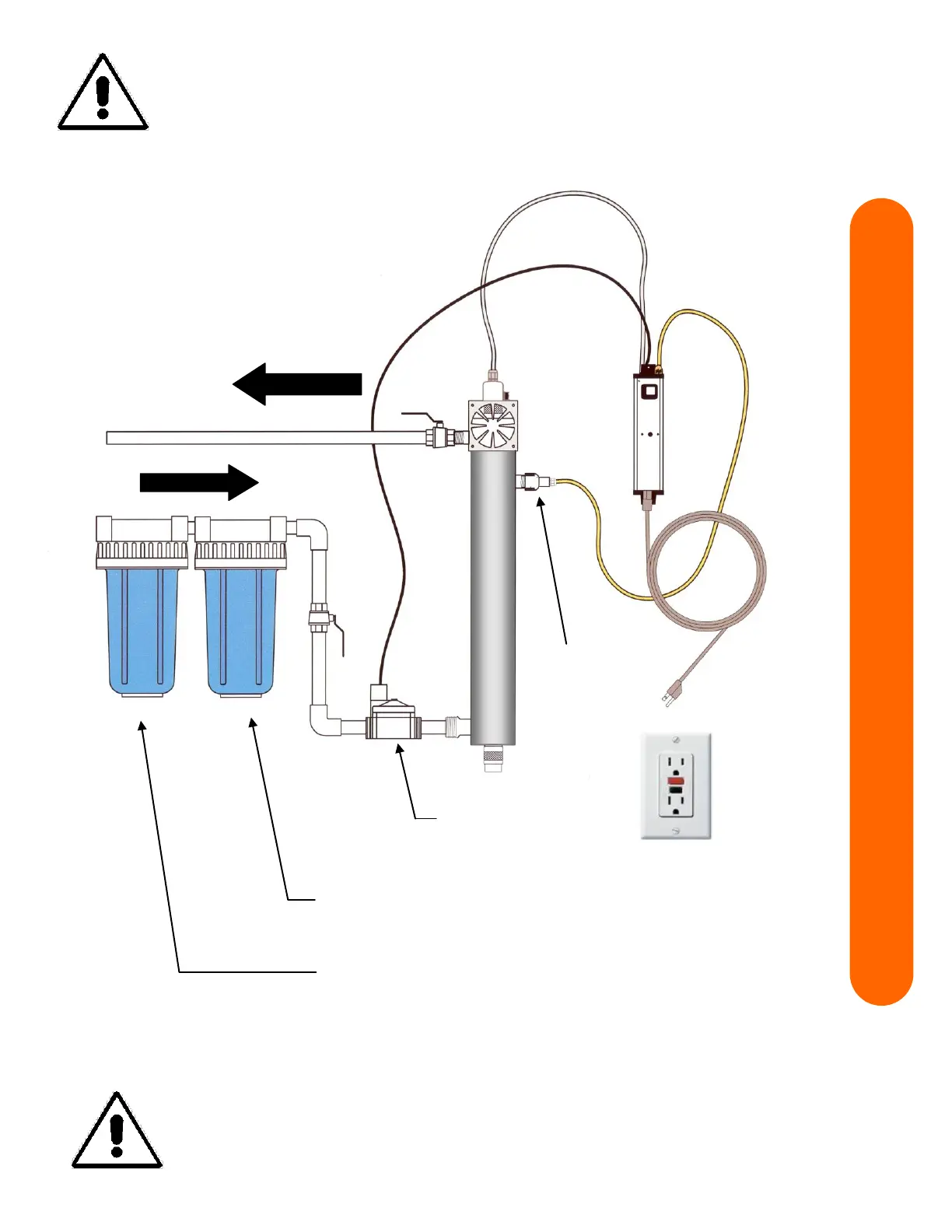
Installation Example - Model 11.40C, 14.40C, & 20.40C
READ INSTALLATION CAUTIONS AND VERIFY
MINIMUM WATER QUALITY REQUIREMENTS BEFORE
PROCEEDING WITH INSTALLATION
OPTIONAL – additional
pre-treatment as required,
5 micron sediment filter –
minimum required pre-treatment
Disinfected water to all
taps and appliances
Select a disinfection system mounting location where a potential leak will not
cause water damage. UVDynamics is not responsible for water damage. When the
disinfection system can only be located where water damage is a possibility, the
installation of a automatic leak detector / shut off device is highly recommended
© COPYRIGHT 2019 UVDynamics - a Castle Circuits Inc. Business Group All RIGHTS RESERVED
 Loading...