0020244064_02 Operating and installation instructions 9
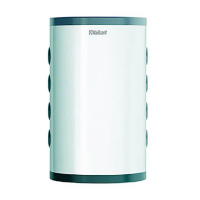
3. Install the three enclosed feet at the bottom of the cyl-
inder.
4. Use the adjustable feet and a spirit level to align the
product.
5 Installation
5.1 Hydraulics installation
5.1.1 Water-side connection
Caution.
Risk of material damage caused by
residues in the pipelines.
Welding remnants, sealing residues, dirt or
other residues in the pipelines may damage
the product.
▶ Flush the heating installation thoroughly
before installing the product.
Caution.
Risk of damage caused by heat transfer
when soldering.
The heat that is transferred during solder-
ing may lead to damage to the expanded
polypropylene around the product and to the
seals on the connectors.
▶ Protect the product's insulating casing.
▶ Do not solder the connectors if these have
been screwed onto the product.
Caution.
Risk of material damage caused by corro-
sion
Due to non-diffusion-tight plastic pipes in the
heating installation, air gets into the heating
water. Air in the heating water causes corro-
sion in the heat generator circuit and in the
product.
▶ If you use non-diffusion-tight plastic pipes
in the heating installation, ensure that no
air gets into the heat generator circuit.
1. Attach a draining cock at the lowest point in the install-
ation.
2. Depending on your installation, connect the circuits in
accordance with the basic diagrams shown below.
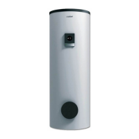
Validity: VPS R 200/1 B
▶ Connect a draining cock to the drain connection on the
cylinder.
▶ If you do not connect a draining cock, attach the drain
plug (1) in order to guarantee the leak-tightness of the
cylinder.
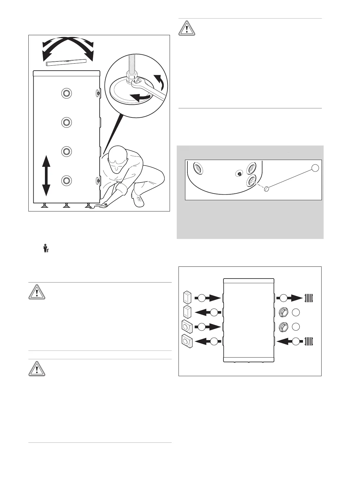
5.1.2 Basic hydraulic connection diagram
5.1.2.1 Case no. 1
1 Heat pump
2 Boiler
3 Heating circuit
4 Plug
 Loading...