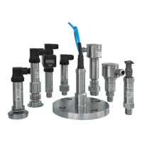
Cavo / Cable
USCITA / OUTPUT 4-20mA
Tecnica 2 fili / 2 wire system:
Filo Rosso / Red Wire = V+ alimentazione / supply
Filo Nero / Black Wire = V- comune / common
Schermo / Shield = Massa / Earth
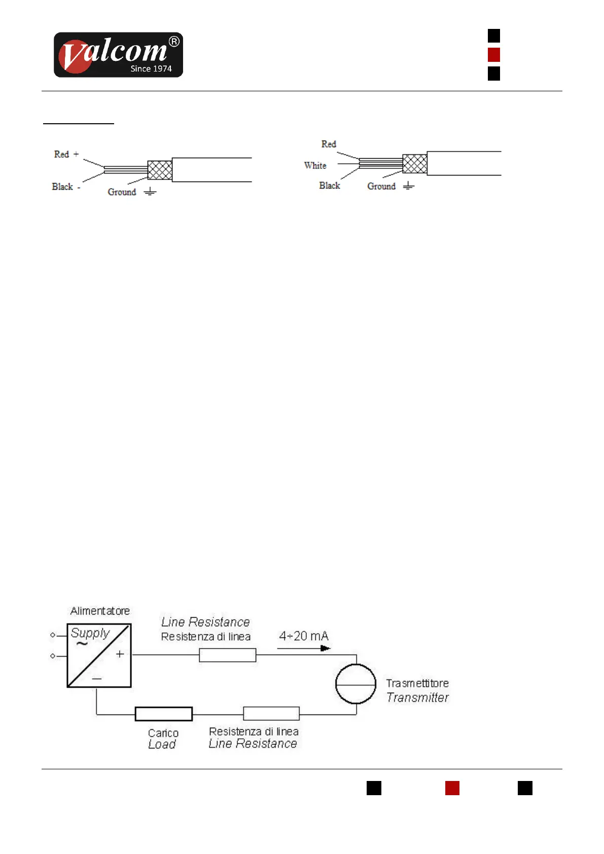
Alimentazione
L’elettronica della serie 27A e 27D necessita di una
tensione di alimentazione tra 10 e 30Vcc.
Lo schema generale di collegamento è
rappresentato in figura 3
Il segnale di uscita dello strumento è standard
4÷20mA in tecnica a 2 fili, proporzionale alla
misura.
Dal grafico di figura 4 è possibile vedere l’ area di
corretto funzionamento dello Strumento.
La tensione minima di alimentazione, tenendo
conto del carico, risulta così dimensionata :
Vcc (min) = 0,02 x R (carico totale in Ohm) + 10Vcc
dove il carico totale è data dalla somma della
resistenza di linea più il carico (come da figura 3)
La sorgente di alimentazione deve essere in grado di
erogare una corrente minima di 23mA
USCITA / OUTPUT 0-10Vdc (0-5Vdc)
Tecnica 3 fili / 3 wire system:
Filo Rosso / Red Wire = V+ alimentazione / supplì
Filo Bianco / White Wire = Vo uscita / output
Filo Nero / Black Wire = V- comune / common
Schermo / Shield = Massa / Earth
Supply
The 27A and 27D series electronics needs a supply
voltage between 10 and 30Vdc
The general wiring scheme is shown in figure 3.
Instrument’s output signal is a 4÷20mA two-wire
system.
Figure 4 shows the transmitter operating area.
Minimum supply voltage, according to the
requested load, is calculated as follow:
Vdc (min) = 0,02 x R (total load in Ohm) + 10Vdc.
where the total load is the sum of line resistance
plus load (as shown in figure 3)
The supply source should give a minimum current of
23mA.
 Loading...