Installation, Operating & Maintenance Instructions
Series 650, DN 100 – 250 (I.D. 4" - 10")
VAT Vakuumventile AG, CH-9469 Haag, Switzerland
Tel ++41 81 771 61 61 Fax ++41 81 771 48 30 Email reception@vat.ch www.vatvalve.com
258550EE
2007-05-11
37/51
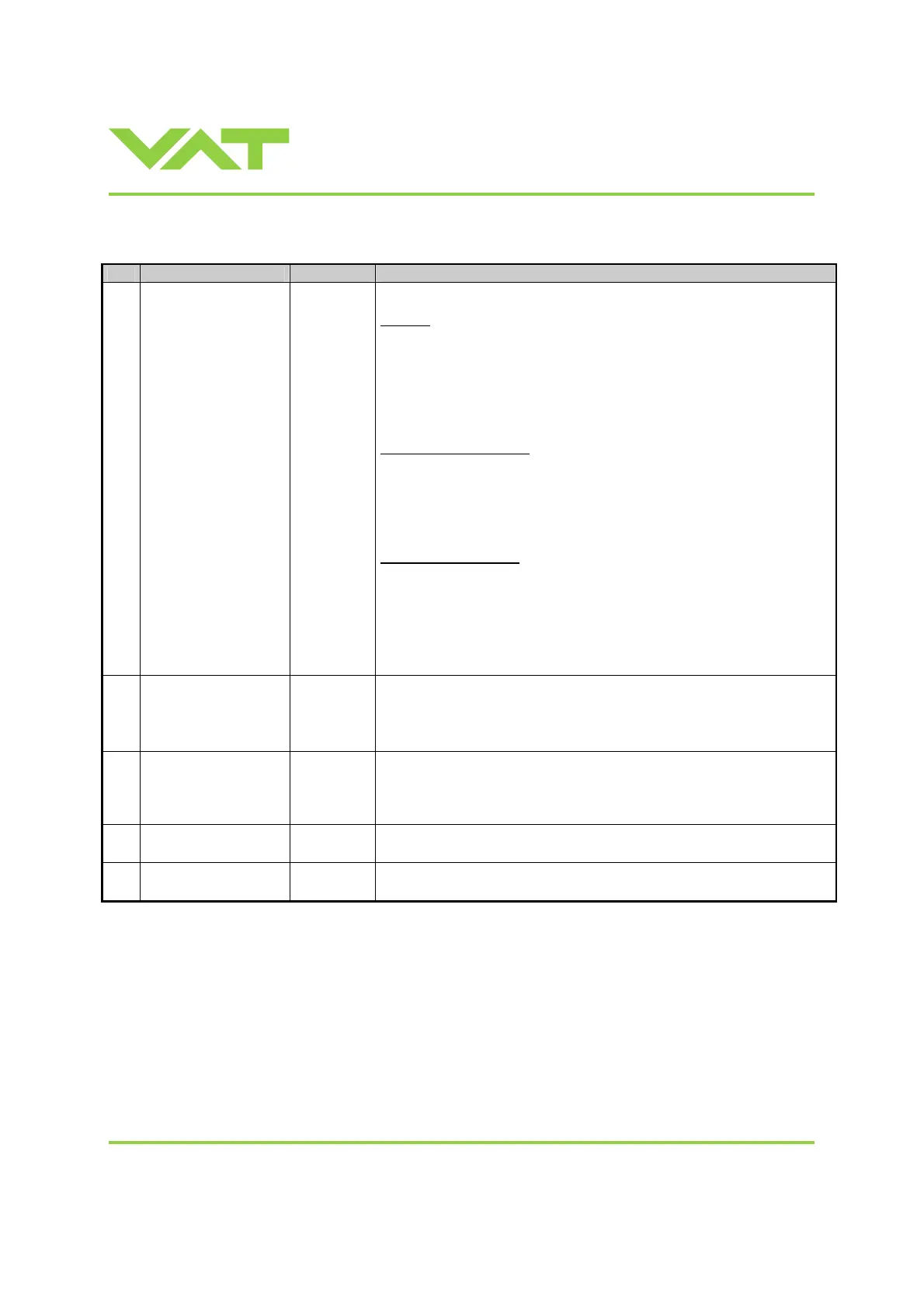
3.11.4 Analog inputs and outputs
Pin Function Signal type
Description
25 SETPOINT
Analog
input
1)
The meaning of the setpoint input depends on the operation mode.
LEARN:
A voltage of 0-
10V shall be applied to this input as pressure limit for learn.
The limit pressure is in linear relation to the applied voltage. 10V relates to
sensor full scale.
In case of 2 sensor operation 10V relates to high range sensor full scale.
Note: To activate pressure limit function for remote operation it must be
configured accordingly. Refer to «3.6.1 Interface configuration»
PRESSURE CONTROL:
A voltage of 0-10V shall be applied to this input as pressure setpoint. The
pressure setpoint is in linear relation to the applied voltage. Depending on
selected SETPOINT RANGE 10V means either sensor full scale or 10%
of sensor full scale.
In case of 2 sensor operation 10V relates to high range sensor full scale.
POSITION CONTROL:
A voltage of 0-10V shall be applied to this input as position setpoint. The
voltage directly controls the position of the pendulum plate. The position is
in linear relation to the applied voltage.
• 0V is related to the most closed (but not isolated) pendulum plate
position
• 10V is related to the fully open pendulum plate position
12
PRESSURE
Analog
output
1)
This output indicates the current pressure as 0-10V. The output voltage is
in linear relation to the pressure. Depending on the selected SETPOINT
RANGE 10V means either sensor full scale or 10% of sensor full scale.
In case of 2 sensor operation 10V relates to high range sensor full scale.
11 POSITION
Analog
output
1)
This output indicates the current pendulum plate position as 0-10V
voltage range. The voltage is in linear relation to the position. 0V is related
to most closed pendulum plate position (valve not necessarily isolated)
and 10V to fully open pendulum plate position.
13 ANALOG GROUND
Analog
ground
Ground for analog input and analog outputs.
1 CHASSIS GROUND
Chassis
ground
Chassis ground connected to case. Shall be used to connect cable shield.
1) Refer to «3.11.1 Schematics» for details about input / output circuit.
 Loading...


