Installation, Operating & Maintenance Instructions
Series 650, DN 100 – 250 (I.D. 4" - 10")
VAT Vakuumventile AG, CH-9469 Haag, Switzerland
Tel ++41 81 771 61 61 Fax ++41 81 771 48 30 Email reception@vat.ch www.vatvalve.com
258550EE
2007-05-11
47/51
5.2.2 Retrofit / replacement procedure
ESD Precaution!
All work on the control and actuating unit has to be done under ESD protected environment to prevent
electronic components from damage!
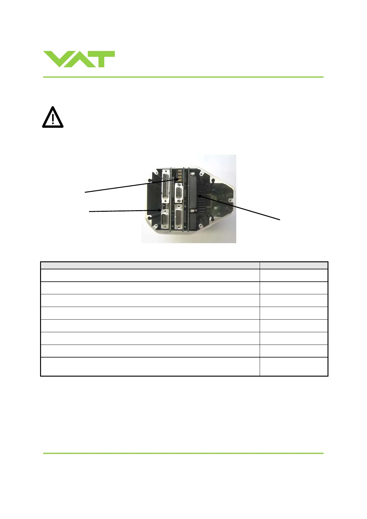
Top view on control and actuating unit with panel removed:
Description Required tool
1. Remove screws from POWER, SENSOR and INTERFACE connectors. open end wrench 4.5 mm
2. Remove panel screws. Phillips screwdriver size 2
3. Lift panel carefully.
4. Disconnect fan cable from board.
5. Replace option board or insert it at free position.
6. Reconnect fan cable to master board (step 4).
7. Tighten panel screws with 1.1 Nm. Phillips screwdriver size 2
8. Tighten screws from POWER, SENSOR and INTERFACE connectors with 1.1
Nm.
open end wrench 4.5 mm
Master board
Interface board
Option board
 Loading...


