1
Testing an EMR
3
System
To perform a Display Head Complete Self-Diagnostic Check
Cycle power to the EMR³ system. To cycle power, turn the power off for at least 20 seconds before turning on
again. During power up, each Display Head tests all its own circuit board hardware. The self-test takes about 25 to
30 seconds. If a failure occurs, an error code is posted on the display. See Startup Error Codes Section of this
Guide.
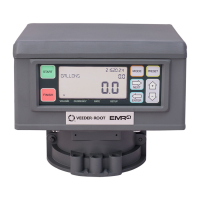
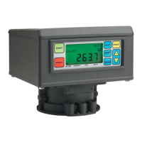
To Test the LCD Display
Simulate a delivery by performing a START and FINISH sequence in Volume or Currency mode. The fueling nozzle
icon will appear after pressing the START key. For a brief period of time, all of the segments will turn on, then off. If
the unit fails to perform this test, press the FINISH key once, then press START and FINISH again. The Display
nozzle icon and display activity noted should then occur. If the display check does not work, then the head will
need to be replaced.
Pulse Encoder Input Check
With the cover open and the unit NOT in the C&C mode, disconnect the spring between the pulse encoder and
the input shaft. Push start and turn the pulse encoder shaft until a nonzero reading appears on the register portion
of the display. Press the FINISH key, the nozzle icon turns off and a delivery ticket is printed. BE SURE TO
RECONNECT THE SPRING BEFORE REPLACING THE LID.
Printer Check
Verify ticket printing by either printing duplicate tickets or by simulating a delivery as noted above. To print a
duplicate ticket, hold the FINISH key down for a few seconds.l
Available Documentation
For EMR3 hardware related details, see the EMR3 Installation Guide, number 577013-758. For information related
to menus or settings, see the EMR3 Setup and Operation Manual, number 577013-766. Descriptions of the
EMR3 System are available on the UL/cUL Control Drawing, document number 331940-016 or the ATEX System
Drawing, document number 331940-004. Veeder-Root documents are available on our web site at
www.veeder.com.
 Loading...