23
RS02
1- Characteristics
Control panel for governing sliding gear moTors/Sperren and road barriers, 12 V dc with 50 W rated power, equipped with inputs for limit switch, encoder
(used for obstacle detection and speed control) integrated receiver and display for programming
The control panel enables:
- customizing the space and speed of deceleration in both opening and closing phases
- equipped with obstacle detection system
- LED for input diagnostics
- removable saved data memory
- integrated receiver with capacity for 200 remote controls (hard coded or rolling code)
- current control for electric motor protection
- log of the last 9 faults or errors.
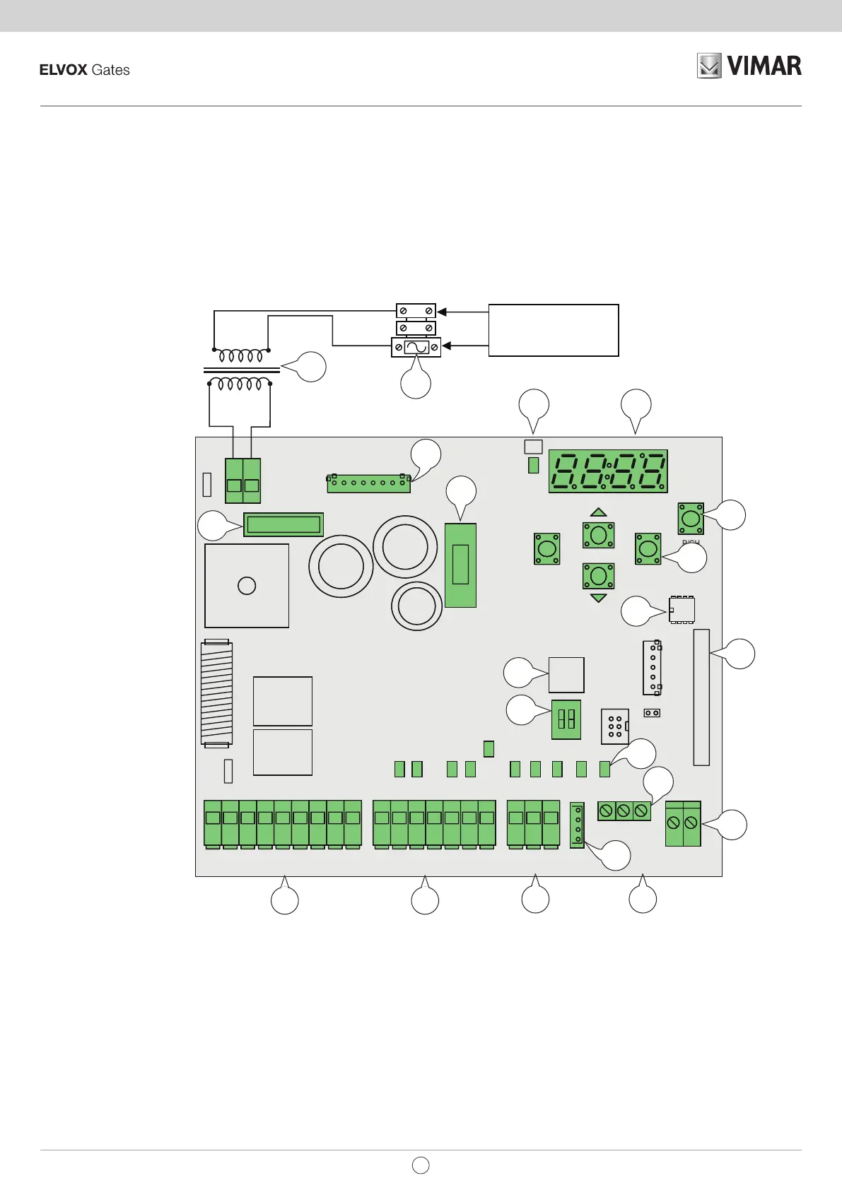
2- Description of the control panel
Key:
1- Transformer primary fuse (2 A delayed)
2- Transformer 230 Vac – 13.5 Vac
3- 20 A fuse protecting motor
4- 3.15 A fuse protecting accessories
5- LED signalling mains power supply
6- Display
7- AP/CH control button
8- Buttons for menu scrolling and programming
9- External memory
10- Radio module
11- LED for input diagnostics
12- Terminal for aerial connection
13- Microprocessor
14- Magnetic encoder connector
15- Removable terminal for connecting the limit switches
16- Removable terminal for connecting the control and safety inputs, control panel supplied with jumpered normally closed inputs.
17- Removable terminal for connecting the motor output, flashing light and accessories power supply
18- Optical encoder connector
19- Dip selection sliding / barrier
20- Connector for emergency battery charger card
Fig. 1
CN8
IBRIDO RX
CN1
SEC
CN7
VA
2
VA1
ELVOX SERIE EC
PT1
25 26
FSC
FST
1
AUX
+VA
-VA
P
P
H
STOP
O
STPA
ENC
-
ANT
CN6
U1
CN2
CN3
APED
DL5DL10 DL6
CN4
FCAPAPCH
DL9
STOP
DL2
FOTO
DL3
STPA
DL1
FCCH
DL
DL
NC1M
NC
DL
NC1
SW1
PROGRAM. MENU'
23 24
CN11
CN9
U2
JP3
123456789 17 18 1910 11 12 13 14 15 16
AC
DL11
AP/CH
P1
P2 P5
P3
P4
OKESC
SE
- E
+ E
8
7
E
E
X
4
E
0
ON
12
D
20 A
F2 (ATO)
F1 (5x20)
T 3.15A
17 16
15
8
3
11
7
5
1
9
4
13
10
19
12
14
18
6
2
20
18
Line
power supply
EN
 Loading...