English
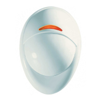
Supervised Wireless PowerCode Flood Detector
Español
Detector Inalámbrico de Inundación PowerCode con Supervisado
Portuguese
Detector Via-rádio de Inundações PowerCode com Supervisão
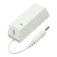
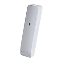
GB/US: TRANSMISSION LED
SP: DIODO LUMINOSO DE TRANSMISIÓN
PT: DIODO LUMINOSO DO TRANSMISSÓR
Fig. 1 - MCT-550
ENGLISH
1. INTRODUCTION
The MCT-550 is a fully supervised indoor, PowerCode flood
detector, used to detect the presence of water based fluids at
any desired location.
The MCT-550 transmitter is designed for wall mounting. The
flood sensor is placed in a location where the presence of water
based fluids, as a result of leakage or flooding, is probable.
Upon
flood detection, a digital message is transmitted, composed of
the detector ’s PowerCode ID followed by various status and other
messages. Alarm and other data are thus forwarded to the alarm
system.
An on-board tamper switch is opened when the cover is
removed. In a tamper situation, a tamper message is
transmitted.
A periodic supervision message is transmitted automatically (see
specifications) to inform the alarm system at regular intervals, of
the unit’s active participation in the system.
An LED lights whenever alarm or tamper events are reported. The
LED does not light while a supervision message is being
transmitted.
Operating power is obtained from an on-board 3 V Lithium battery.
A weak battery will cause a “low battery” report to be added to any
message transmitted.
2. SPECIFICATIONS
Compatibility: Compatible with PowerMax and PowerMax+ alarm
systems, MCR-308 receiver or any other PowerCode alarm system.
Frequency (MHz): 315, 433.92, 868.95, 869.2625 or other
frequency according to local requirements.
Transmitter's ID Code: 24-bit digital word, over 16 million
combinations, pulse width modulation.
Overall Message Length: 36 bits
Message Repetition: One-shot transmission (default) or once
every 3 minutes (selectable).
Supervision: Signaling at 60-minute intervals (U.S. version) or 15
minute interval (UK version), or according to the local standards.
Response to Tamper Event: Tamper report every 3 minutes
(until the tamper switch is restored).
Power Source: 3V Lithium battery, Panasonic type CR-2 or
equivalent.
Nominal Battery Capacity: 750 mAh
Current Drain: 6µA STBY, 17mA average in operation (including LED)
Battery Life with LED on: 3 years (for typical use)
Battery Supervision: Automatic reporting of battery condition
data as part of any transmission.
ALARM REPORT:
Every 20 sec. for the first 3 minutes.
Every 3 min. for the next 27 minutes.
After this period the supervision message will include alarm signal until
the event comes to an end.
Length of Flood Sensor Cable: 3 meters (10 ft)
Weight of Flood Sensor Cable: Approx. 60 gr.
Operating Temperature: 0°C to 49°C (32°F to 120°F).
Dimensions: 81 x 22 x 23.5 mm (3-3/16 x 7/8 x 15/16 in.).
Weight (including battery, without cable): 45 g (1.6 oz)
Standards: Meets FCC Part 15, Directive 1999/5/EC and EN
50131-1 Grade 1 Class II.
This device complies with Part 15 of the FCC Rules and RSS-210 of
Industry and Science Canada. Operation is subject to the following
two conditions: (1) This device may not cause harmful interference,
and (2) this device must accept any interference received, including
interference that may cause undesired operation.
This
device complies with the essential requirements and provisions
of Directive 1999/5/EC of the European Parliament and of the
Council of 9 March 1999 on radio and telecommunications terminal
equipment.
3. INSTALLATION
A. Attach the flood sensor near the floor.
B. Secure the flood sensor and its cable to the wall using the three
wire clamps. One clamp should be fastened immediately above
the flood sensor. The flood sensor should be installed only in a
vertical position, and facing downward. The remaining two
clamps can be used as required (Figures 2 and 3).
Note: To provide better protection against rats, it is recommended
that the flood sensor cable be placed inside a metal/plastic pipe.
C. Attach
the transmitter to the wall. The transmitter should be
placed as high up as possible on the wall to improve
communication and to prevent the transmitter itself from coming
into contact with water in the event of flooding.
D. Remove the case closure screw (Figure 4), then remove the
unit's cover (Figure 5).
E. Flex out the circuit board retainer (Figure 6) and detach the
circuit board from the base.
F. Hold the base against the mounting surface and mark the 2
drilling points through the mounting holes.
G. Drill the holes and fix the base to the wall using the 2 screws
with countersunk heads supplied in the package.
CAUTION! Screws with other type or size of head may short
circuit the bottom side of the printed circuit board.
H. Insert the edge of the P.C. board with the RF module into the
edge supports, and press the other edge against the flexible
retainer until it snaps home with a click.
I. Clamp the two wires of the flood sensor cable into the
auxiliary input terminals, as shown in Figure 7 (the wires can
be inserted in any order).
4. PREPARATION FOR USE
4.1 The Function Switches
A. Switch Functions
The MCT-550 has a 4-position DIP switch function selector (Figure 8).
B. Setting the Switches
Set the function switches as desired prior to applying power. Use a
ball point pen or other pointed object to shift the switch levers. The
ON position is indicated by the arrow on the switch body.
Table 1. Getting acquainted with the function selector
Sw- Function Pos. Selected Option Default
SW1
- -
SW1 should remain always in
OFF position
OFF
SW2
- -
SW2 should remain always in
ON position
ON
SW3
Restore reports
enable/disable
ON
OFF
Restore events reported
Restore events not reported
ON
SW4
- - -
-