I
NEXT
PIR
MCW,
NEXT
K9-8S
MCW
I
GB/US:
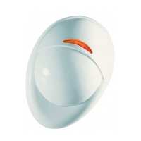
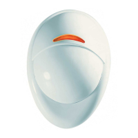
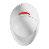
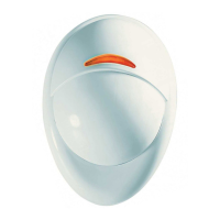
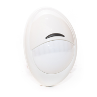
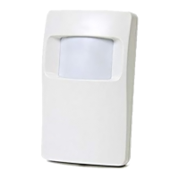
Lens
SP:
Lente
PT:
Lente
GB/US:
Walk-Test
LED
SP:
LED
de
modo
de
pruebas
PT:
LED
do
teste
de
passagem
~
Visonia
Fig.
1 -
NEXT
PIR
MCW
/
NEXT
K9-8S
MCW
Detectores PIR Digital / Inmune a mascotas inalambricos -
Instrucciones de instalaci6n
Wireless, PowerCode Digital PIR / Pet Immmune PIR
Detectors - Installation Instructions
Detector PIR Digital / Imune a Animais Via radio -
Instru<;:6es
de Instala ao
ENGLISH
1. INTRODUCTION
The NEXT PIR
MCW
and NEXT K9-85 MCW (pet immune) are
microprocessor-controlled wireless digital PIR detectors.
NEXT
is
a registered mark of
Vi
sonic Ltd.
The detectors features are as follows:
• Cylindrical lens with uniform detection sensitivity throughout its
operating range, up to
12
meters (40 ft).
• NEXT PIR MCW includes wall creep zone protection.
•
In
NEXT K9-85 MCW, Target Specific
Imaging™
(TSI) technology
is
used for distinction between human beings and pets weighing up to
38
kg
(85Ib).
• Incorporates a fully supervised PowerCode transmitter.
• The advanced True
Motion
Recognition™ algorithm (patented)
allows distinguishing between the true motion
of
an
intruder and any
other disturbances which may cause false alarms.
• Sophisticated frequency domain digital signal processing.
• No vertical adjustment
is
needed.
• An on-board motion event jumper determines whether 1 or 2
consecutive motion events trigger
an
alarm.
• After detection, the detector disarms itself to save battery power.
It
rearms (reverts to the ready state) if there
is
no subsequent
detection throughout the following 2-minute period.
• An optional version provides better protection for systems
compliant with DD243. After initial detection, the detector
is
capable of 6 additional detections for a period of 5 minutes.
Further detection
is
possible only if no movement occurs during the
following 2 minutes. The detector will revert to the initial state if
there
is
no movement for
an
additional 5 minutes.
• Very low current consumption.
• Microprocessor-controlled temperature compensation.
• Sealed chamber protects the optical system.
• Front cover tamper switch.
• Back tamper switch (option - NEXT PIR T MCW).
• White light protection.
• Elegantly styled, sturdy case.
For
UL
installations:
The detector is for use with
UL
listed control
unit PowerMax+ only. Pet immunity has not been evaluated
by
UL.
2. SPECIFICATIONS
Detector Type: Dual element low-noise pyroelectric
sensor
Lens
Data
No.
of
Curtain
Beams:
NEXT PIR
MCW
9 +
5,
NEXT K9-85
MCW
9
Max. Coverage:
12
x
12
m.
(40 x 40 ft) I 90°
Pet
Immunity
(NEXT K9-85 MCW Only): Up
to
38
kg
(85
Ib).
ELECTRICAL
Internal Battery: 3V
Lithium
battery,
type
CR-123A.
For
UL
installations,
use
Panasonic
or
Sanyo
only.
Nominal
Battery
Capacity:
1450 mA/h.
Standby
Current
Drain: Approx. 0.025
mAo
Transmit
Current
Drain:
20 mA (including LED).
Battery
Life
(with
LED
on):
Typically over 3 years.
Battery
Power
Test: Performed immediately upon battery insertion
and periodically after every several hours.
FUNCTIONAL
True
Motion
Event
Verification:
2 position selector - 1 (OFF) or 2
(ON) motion events.
Alarm
Period:
3 seconds.
Visual
Indications:
LED
Lights
for about 3 seconds upon transmission of alarm &
tamper messages and upon motion detection
in
the walk test mode.
LED
Flashes
during the power-up stabilization period, or after
restoring (pressing) the tamper switch.
LED Does
not
light
upon transmission of supervision messages.
Rearm Timer: Rearms the detector 2 minutes after the last alarm.
Timer disabled
in
the walk test mode - not applicable for the DD243
version (see section
1).
WIRELESS
Frequency
(MHz): 315 (U.S. version),
43392,
868.95, 869.2625
or
other frequency according to local requirements.
Transmission
Sequence:
3 data bursts at variable intervals within 3
seconds.
Encoding:
24-bit ID, over 16 million possible combinations.
Total
Message
Length:
36
bits.
Tamper
Alert:
Reported when a tamper event occurs and
in
any
subsequent message, until the tamper switch
is
restored.
Supervision
Message: Signaling at 60 minutes interval (U.S. version).
15
minute interval (UK version) or according
to
local standards.
MOUNTING
Height:
1.8 - 2.4 m
(6
- 8
ft).
For NEXT K9-85 MCW, the recommended
height
is
up
to
2.1
m
(7
ft)
Installation
Options:
Surface or corner.
ACCESSORIES:
BR-1: Surface mounted swivel bracket, adjustable 30° down and 45°
lefU45° right.
BR-2: BR-1 with a corner adapter
BR-3: BR-1 with a ceiling adapter
ENVIRONMENTAL
RFI
Protection:
>20 Vim up to 1000 MHz.
Operating
Temperatures:
-10°C to 50°C (14°F to 122°F).
Storage
Temperatures:
-20°C to 60°C (-4°F to 140°F).
Compliance with Standards:
Designed
to
meet
FCC
Part
15
and
Directive
1999151EC
of
the
European
Parliament
En
50131-1
Grade 2
(detector
with
back
tamper
switch)
I
Grade
1
(detector
without
back
tamper
switch),
Class
II
Telefication
is
the
certification
body
for
NEXT
PIR
MCW & NEXT
PIR
T
MCW
PHYSICAL
Size
(H
x W x D): 94.5 x 63.5 x 53.0 mm (3-11/16 x 2-1/2 x 2-1/16").
Weight
(with
battery): 70 9 (2.5 oz).
Color:
White.
PATENTS: U.S. Patents
5,693,943.6,211,522.
D445,709 (another
patent pending).
3. INSTALLATION
3.1
General
Guidance
(see
fig. 3)
1.
Keep away from heat sources.
5.
Keep wiring away from power
2.
Do not expose to air drafts. cables.
3.
Do not install outdoors.
6.
Do
not install behind partitions.
4.
Avoid direct sunshine.
7.
Mount
on
solid stable surface.
3.2 Installation Procedure
1.
Mounting - see fig.
4.
2.
Battery installation (see fig. 4)
3.
Detector reset:
With the battery
in
place, press both tamper switches
simultaneously (see fig. 4) and release them. The front LED will
flash for about 2 minutes until the detector stabilizes.
Note: The detector transmits a low battery signal upon detection of
low voltage. It
is
recommended to wait about 1 minute after battery
removal, before inserting the new battery.
4.
Enrolling:
Enroll the detector's ID into the alarm system memory according to
the alarm system insallation instructions. When you are instructed
to transmit, press both tamper switches again and release them.
You may enroll the detector's ID while the detector's LED flashes
5.
Jumpers settings - see fig.
5.
6.
Walk-test the coverage area - see fig.
2.
Walk across the far end of
coverage pattern in both directions. The LED should light for 2-3
seconds each time your motion
is
detected.
Important!
Instruct the user to walk test at least once a week to
verify proper function of the detector.
D-3591-EPS
I
NEXT
PIR
MCW,
NEXT
K9-8S
MCW
I
GB/US:
Lens
SP:
Lente
PT:
Lente
GB/US:
Walk-Test
LED
SP:
LED
de
modo
de
pruebas
PT:
LED
do
teste
de
passagem
~
Visonia
Fig.
1 -
NEXT
PIR
MCW
/
NEXT
K9-8S
MCW
Detectores PIR Digital / Inmune a mascotas inalambricos -
Instrucciones de instalaci6n
Wireless, PowerCode Digital PIR / Pet Immmune PIR
Detectors - Installation Instructions
Detector PIR Digital / Imune a Animais Via radio -
Instru<;:6es
de Instala ao
ENGLISH
1. INTRODUCTION
The NEXT PIR
MCW
and NEXT K9-85 MCW (pet immune) are
microprocessor-controlled wireless digital PIR detectors.
NEXT
is
a registered mark of
Vi
sonic Ltd.
The detectors features are as follows:
• Cylindrical lens with uniform detection sensitivity throughout its
operating range, up to
12
meters (40 ft).
• NEXT PIR MCW includes wall creep zone protection.
•
In
NEXT K9-85 MCW, Target Specific
Imaging™
(TSI) technology
is
used for distinction between human beings and pets weighing up to
38
kg
(85Ib).
• Incorporates a fully supervised PowerCode transmitter.
• The advanced True
Motion
Recognition™ algorithm (patented)
allows distinguishing between the true motion
of
an
intruder and any
other disturbances which may cause false alarms.
• Sophisticated frequency domain digital signal processing.
• No vertical adjustment
is
needed.
• An on-board motion event jumper determines whether 1 or 2
consecutive motion events trigger
an
alarm.
• After detection, the detector disarms itself to save battery power.
It
rearms (reverts to the ready state) if there
is
no subsequent
detection throughout the following 2-minute period.
• An optional version provides better protection for systems
compliant with DD243. After initial detection, the detector
is
capable of 6 additional detections for a period of 5 minutes.
Further detection
is
possible only if no movement occurs during the
following 2 minutes. The detector will revert to the initial state if
there
is
no movement for
an
additional 5 minutes.
• Very low current consumption.
• Microprocessor-controlled temperature compensation.
• Sealed chamber protects the optical system.
• Front cover tamper switch.
• Back tamper switch (option - NEXT PIR T MCW).
• White light protection.
• Elegantly styled, sturdy case.
For
UL
installations:
The detector is for use with
UL
listed control
unit PowerMax+ only. Pet immunity has not been evaluated
by
UL.
2. SPECIFICATIONS
Detector Type: Dual element low-noise pyroelectric
sensor
Lens
Data
No.
of
Curtain
Beams:
NEXT PIR
MCW
9 +
5,
NEXT K9-85
MCW
9
Max. Coverage:
12
x
12
m.
(40 x 40 ft) I 90°
Pet
Immunity
(NEXT K9-85 MCW Only): Up
to
38
kg
(85
Ib).
ELECTRICAL
Internal Battery: 3V
Lithium
battery,
type
CR-123A.
For
UL
installations,
use
Panasonic
or
Sanyo
only.
Nominal
Battery
Capacity:
1450 mA/h.
Standby
Current
Drain: Approx. 0.025
mAo
Transmit
Current
Drain:
20 mA (including LED).
Battery
Life
(with
LED
on):
Typically over 3 years.
Battery
Power
Test: Performed immediately upon battery insertion
and periodically after every several hours.
FUNCTIONAL
True
Motion
Event
Verification:
2 position selector - 1 (OFF) or 2
(ON) motion events.
Alarm
Period:
3 seconds.
Visual
Indications:
LED
Lights
for about 3 seconds upon transmission of alarm &
tamper messages and upon motion detection
in
the walk test mode.
LED
Flashes
during the power-up stabilization period, or after
restoring (pressing) the tamper switch.
LED Does
not
light
upon transmission of supervision messages.
Rearm Timer: Rearms the detector 2 minutes atter the last alarm.
Timer disabled
in
the walk test mode - not applicable for the DD243
version (see section
1).
WIRELESS
Frequency
(MHz): 315 (U.S. version),
43392,
868.95, 869.2625
or
other frequency according to local requirements.
Transmission
Sequence:
3 data bursts at variable intervals within 3
seconds.
Encoding:
24-bit ID, over 16 million possible combinations.
Total
Message
Length:
36
bits.
Tamper
Alert:
Reported when a tamper event occurs and
in
any
subsequent message, until the tamper switch
is
restored.
Supervision
Message: Signaling at 60 minutes interval (U.S. version).
15
minute interval (UK version) or according
to
local standards.
MOUNTING
Height:
1.8 - 2.4 m
(6
- 8
tt).
For NEXT K9-85 MCW, the recommended
height
is
up
to
2.1
m
(7
tt)
Installation
Options:
Surface or corner.
ACCESSORIES:
BR-1: Surface mounted swivel bracket, adjustable 30° down and 45°
lefU45° right.
BR-2: BR-1 with a corner adapter
BR-3: BR-1 with a ceiling adapter
ENVIRONMENTAL
RFI
Protection:
>20 Vim up to 1000 MHz.
Operating
Temperatures:
-10°C to 50°C (14°F to 122°F).
Storage
Temperatures:
-20°C to 60°C (-4°F to 140°F).
Compliance with Standards:
Designed
to
meet
FCC
Part
15
and
Directive
1999151EC
of
the
European
Parliament
En
50131-1
Grade 2
(detector
with
back
tamper
switch)
I
Grade
1
(detector
without
back
tamper
switch),
Class
II
Telefication
is
the
certification
body
for
NEXT
PIR
MCW & NEXT
PIR
T
MCW
PHYSICAL
Size
(H
x W x D): 94.5 x 63.5 x 53.0 mm (3-11/16 x 2-1/2 x 2-1/16").
Weight
(with
battery): 70 9 (2.5 oz).
Color:
White.
PATENTS: U.S. Patents
5,693,943.6,211,522.
D445,709 (another
patent pending).
3. INSTALLATION
3.1
General
Guidance
(see
fig. 3)
1.
Keep away from heat sources.
5.
Keep wiring away from power
2.
Do not expose to air drafts. cables.
3.
Do not install outdoors.
6.
Do
not install behind partitions.
4.
Avoid direct sunshine.
7.
Mount
on
solid stable surface.
3.2 Installation Procedure
1.
Mounting - see fig.
4.
2.
Battery installation (see fig. 4)
3.
Detector reset:
With the battery
in
place, press both tamper switches
simultaneously (see fig. 4) and release them. The front LED will
flash for about 2 minutes until the detector stabilizes.
Note: The detector transmits a low battery signal upon detection of
low voltage. It
is
recommended to wait about 1 minute after battery
removal, before inserting the new battery.
4.
Enrolling:
Enroll the detector's ID into the alarm system memory according to
the alarm system insallation instructions. When you are instructed
to transmit, press both tamper switches again and release them.
You may enroll the detector's ID while the detector's LED flashes
5.
Jumpers settings - see fig.
5.
6.
Walk-test the coverage area - see fig.
2.
Walk across the far end of
coverage pattern in both directions. The LED should light for 2-3
seconds each time your motion
is
detected.
Important!
Instruct the user to walk test at least once a week to
verify proper function of the detector.
D-3591-EPS