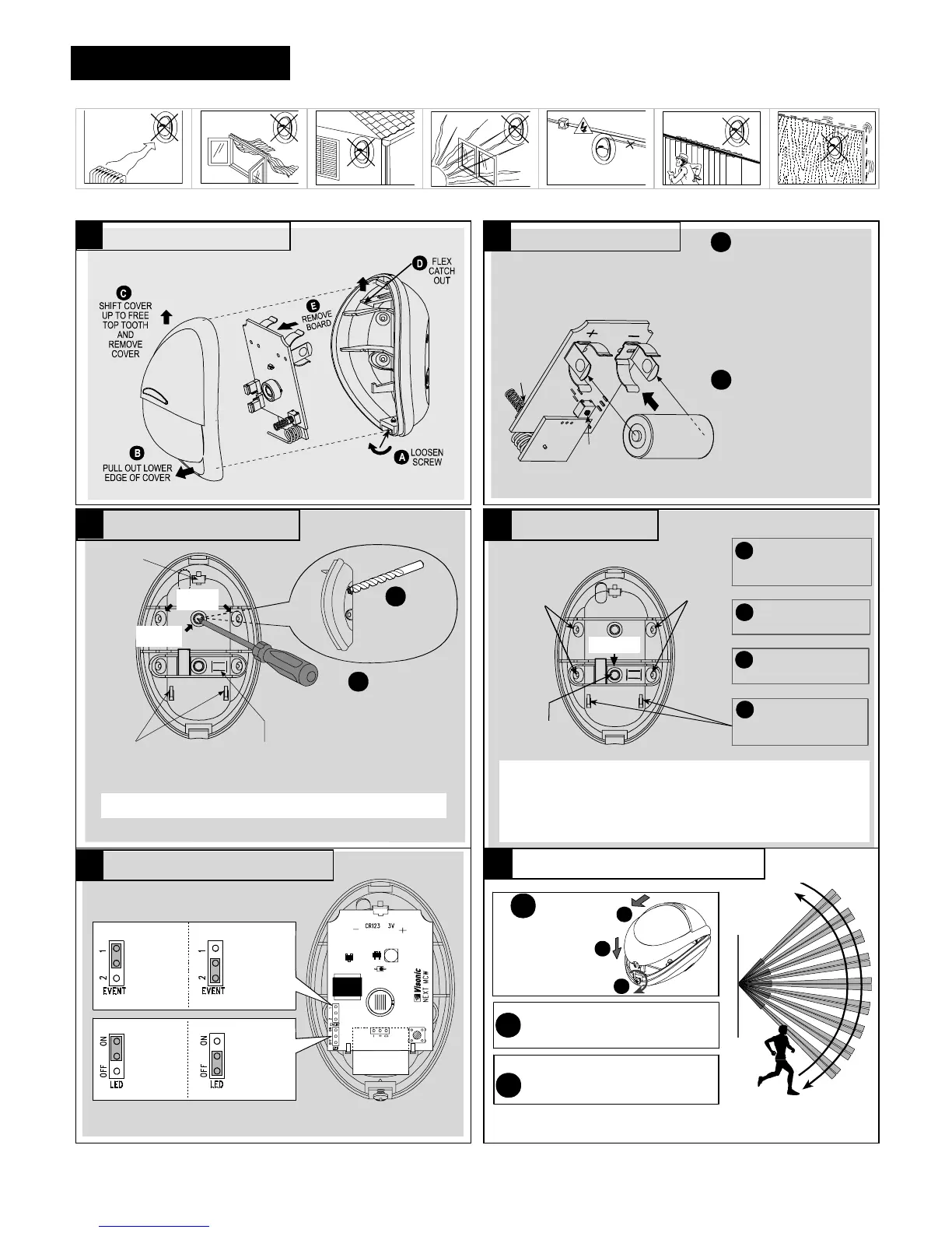
RESET:
With the battery in
place, press both tamper
switches simultaneously
and release them. The
LED at the front will flash
for about 2 minutes until
the detector stabilizes.
Note: The de]tector transmits
a low battery signal upon
detection of low battery.
Note:
It is recommended to wait
about 1 minute before inserting
the new battery.
A
B
BACK
TAMPER
SWITCH
(OPTION)
FRONT
TAMPER
SWITCH
OBSERVE
POLARITY !
ENROLL:
Approach the
control panel and
enroll the
detector’s ID into the control
panel’s memory as shown in
the panel’s installation
manual. When required to
transmit, press both tamper
switches again and release
them.
You may enroll the detector’s
ID while the detector’s LED
flashes.
USE A SCREWDRIVER TO PIERCE
SURFACE OR CORNER KNOCK-
OUTS, AS REQUIRED.
A
USE A LARGE
DIAMETER DRILL
BIT TO DE-BURR
THE OTHER SIDE
B
SUPPORTS
FOR BOTTOM
EDGE OF PCB
CORNER
(2 OF 4)
SURFACE
(1 OF 2)
BREAK-AWAY
SEGMENT (BACK TAMPER
SWITCH ACTUATOR - OPTION)
TOP
CATCH
FOR PCB
Attention! Lean the rear part of the break-away segment against a
piece of wood while piercing its knockouts.
B
INSERT TWO DOWELS AND
C
INSERT THE BOTTOM EDGE
D
MARK TWO DRILLING
A
SINGLE-
SIDE, 45°
ANGLED
MOUNT
SURFACE
MOUNT
(1 OF 2)
ATTACH THE BASE TO THE
WALL WITH TWO SCREWS.
OF THE LARGE P.C. BOARD
UNDER THE TABS & PRESS
THE TOP EDGE IN.
POINTS AND DRILL HOLES
IN WALL.
SINGLE-
SIDE, 45°
ANGLED
MOUNT
BREAK-AWAY
SEGMENT
FOR TAMPER PROTECTION,
THE BREAK-AWAY SEGMENT
MUST BE ATTACHED TO
WALL.
1.8 - 2.4 m (6 - 8 ft) above ground
Attention!
The unit has a back tamper switch (option) under the PCB. As
long as the PCB is seated firmly within the base, the switch will be pressed
against a metal spring piece attached to the base.
Be sure to fasten the break-away segment to the wall with the screws
going through the metal spring and the break-away base segment.
If
the detector is forcibly removed from the wall, this segment will break away
from the base, causing the tamper switch to open and send a tamper alarm.
1 EVENT:
FAST
RESPONSE
2 EVENTS:
HIGHEST
FALSE
ALARM
PROTECTION
ON:
LED
ENABLED
OFF:
LED
DISABLED
IMPORTANT!
INSTRUCT THE USER TO WALK- TEST AT
LEAST ONCE A WEEK TO ASSURE PROPER
FUNCTION OF EACH DETECTOR.
B
WALK ACROSS THE FAR END OF COVERAGE
PATTERN IN BOTH DIRECTIONS. THE
INDICATOR SHOULD LIGHT FOR 2-3 SECONDS
EACH TIME YOUR MOTION IS DETECTED.
C
A
MOUNT THE COVER,
CLOSE IT AND
TIGHTEN THE
SCREW.
WAIT FOR THE DETECTOR
TO STABILIZE (THE LED
STOPS FLASHING).
1
2
3
Note: After closing the cover the detector enters a 15 minute walk-test mode.
In this mode the LED will flash each time a detection occurs, regardle
ss
of LED

 Loading...