30
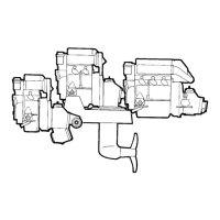
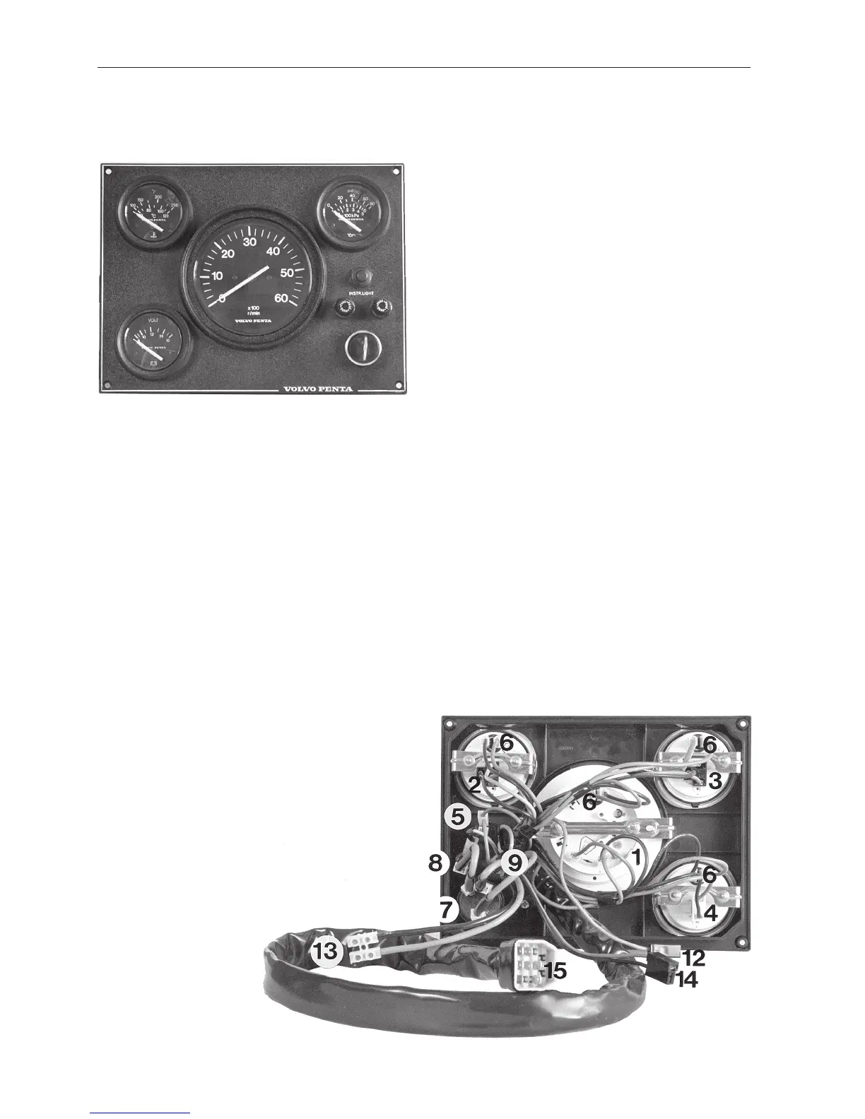
Wiring Diagram 251DOHC
With Instrument panel alternative 2
Cable colour code
SB = Black
PU = Purple
LBN = Light brown
R = Red
GR = Grey
LBL = Light blue
R/Y = Red/Yellow
BN = Brown
W = White
Y = Yellow
Cable cross sections
AWG mm
2
16 1.5
13 2.5
10 6.0
8 10.0
1. Tachometer
2. Oil pressure gauge
3. Temperature gauge, coolant
4. Voltmeter
5. Switch, instrument lighting
6. Instrument lighting
7. Key switch (B=30, S=50, I=15)
8. Fuse 8 A
9. Fuse 8 A
10. Contact terminal neutral position switch
(option/accessory)
11. Contact terminal safety switch (accessory)
12. Connector instrument lighting accessory
13. Connector power output, maximum 20 A
14. Connector power output, maximum 5 A
(main panel + flying bridge panel)
15. Connector, engine–instrumentation
16. Automatic fuse 40A
17. Main switch (option)
18. Battery
19. Temperature sensor
20. Oil pressure sensor
21. Distributor
22. Electronic ignition unit
23. Engine speed (RPM) sensor, ignition system
24. Relay
25. Starter motor
26. Generator
27. Ground terminal
28. Resistor
29. Solenoid valve, carburettor
 Loading...