42
Wiring diagram
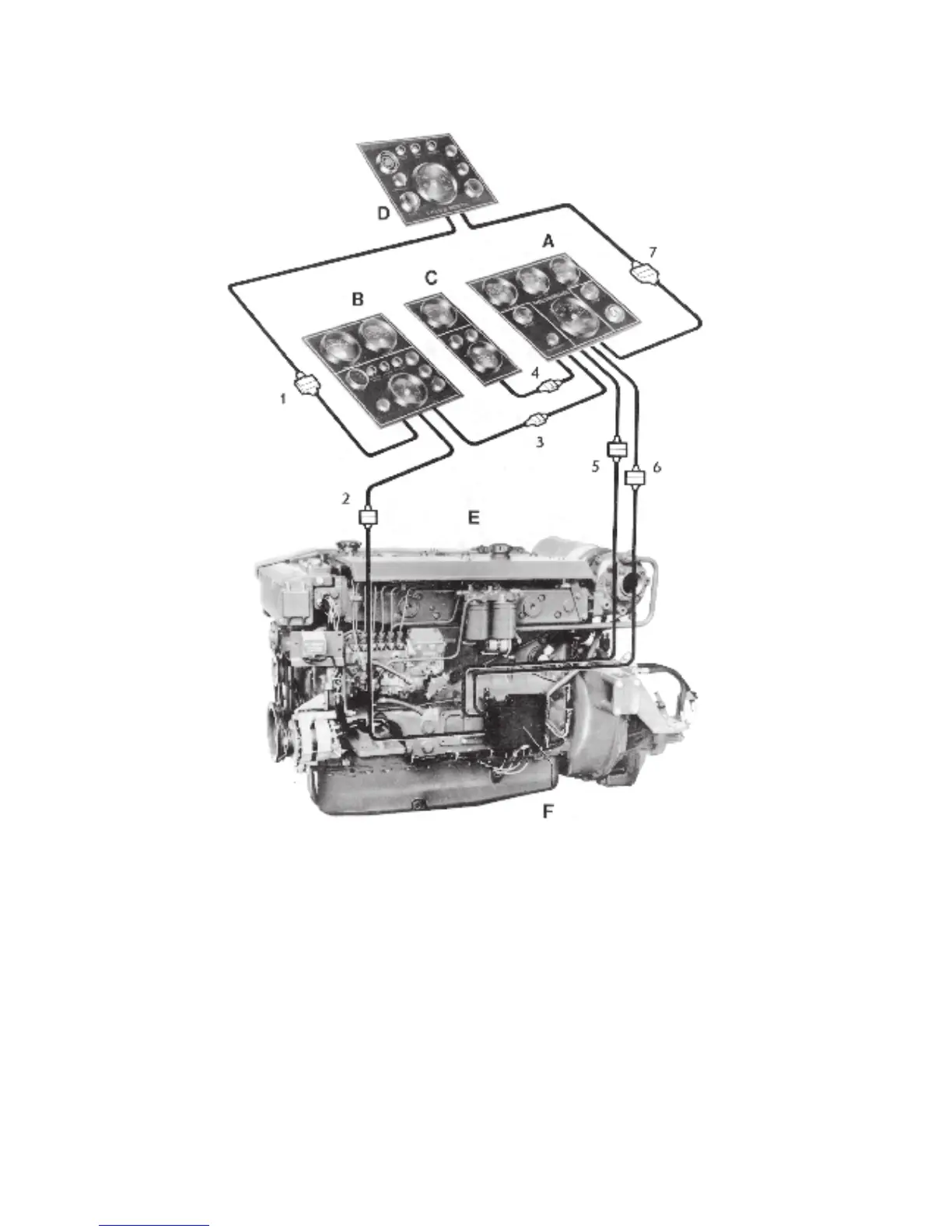
Fig. K1. Block diagram (same for all engines in this book)
A. Basic instrument panel
B. Panel with supplementary instruments (alarm, etc)
C. Panel with fuel gauge and rudder indicator
D. Flying Bridge instrument panel
E. Engine
F. Connection box with fuses
1. Contact (male and female) Red, 8-pole
2. Contact (male and female) Red, 8-pole
3. Contact (male and female) Black, 4-pole
4. Contact (male and female) Black, 4-pole
5. Contact (male and female) Black, 8-pole
6. Contact (male and female) Black, 8-pole
7. Contact (male and female) Green, 8-pole
Male and female contacts belonging together have the same
colour.
If panel D is fitted but not B, contact No. 1 from the Flying
Bridge instrument panel is wired to contact No. 2 from the
engine. However, contacts Nos. 1 and 7 should not be wi-
red together when panel D is not fitted.
When only the basic instrument panel A is fitted, contacts 5
and 6 only are wired together.
Contacts left over should not be wired together but should
be insulated and hung up and protected individually. Ca-
bles should not be cut.
 Loading...