Group 38 Fault Codes, Instrument Cluster Specifications
Specifications
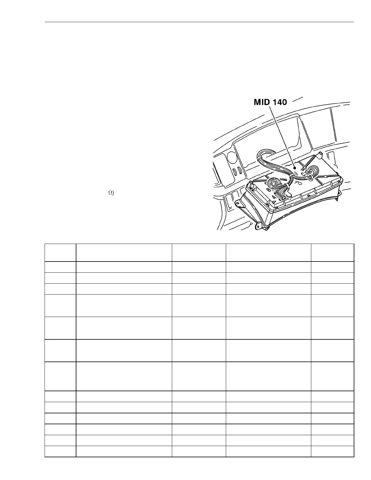
Instrument Cluster, Signal Descriptions
Connector A (22–pin Green) - with breakout box connected between
the instrument cluster (MID140) and cable harness
Requirements:
•
Breakout box 9998699 connected to adapter
9998533 between the instrument cluster and cable
harness. Use extension cable 9990062 if needed.
•
Instrument cluster connected.
•
Ignition key in the drive position.
•
Engine switched off.
•
Measuring voltage using the multimeter.
Notes:
V = direct current voltage (V)
V
bat
= battery voltage
R = resistance in ohms (
)
W3005144
Pin Signal type Measurement
points
Nominal value Other
A1 Power supply (BAT+) A1 - A2 V ≈ V
bat
A2 Ground A2 - ground V≈ 0V
A3 Ignition supply, (DR or key ON) A3 - A2) V ≈ V
bat
A4 Stalk switch, SELECT A4 - A2 V ≈ 0V
V ≈ V
bat
(SELECT active)
A5 Stalk switch, ESCAPE A5 - A2 V ≈ 0V
V ≈ V
bat
(ESCAPE active)
A6 Stalk switch, ARROW UP A6 - A2 V ≈ 0V
V ≈ V
bat
(ARROW UP active)
A7 Stalk switch, ARROW DOWN A7 - A2 V ≈ 0V
V ≈ V
bat
(ARROW DOWN ac-
tive)
A8 Not used
A9 Not used
A10 SAE J1939-3 High A10-A2 V ≈ 0-5V
A11 Not used
A12 Ref Ground for sensor A12-A2 V ≈ 0V
A13 Not used
3
 Loading...