10
3
CAN Router
CAN Repeater
Components
3.2.1 Variants of the CAN repeater
3.3 Pin assignments
3.4 Pressure sensor 441 044 101 0 / 102 0
The pressure sensor generates the nominal brake pressure value as a CAN signal
on towing vehicles with no CAN line or on overlength trailers in order to meet the
necessary timing requirements in accordance with ECE R 13.
In connection with the Trailer EBS E1, the external pressure sensor is connected to
the yellow hose fitting and to connection Y "Pressure sensor" of the CAN router/-
repeater. With a Trailer EBS of the D generation, the pressure sensor is connected
to the "IN/OUT 2" connector of the T-EBS modulator.
!
As of version 1.5 of the Trailer EBS E (production date from CW 49/2009), in the
diagnostic software "Trailer EBS E" with connected external pressure sensor on
the CAN router/-repeater, select setting: "Nominal pressure sensor on R/R" to
improve the communication between the devices.
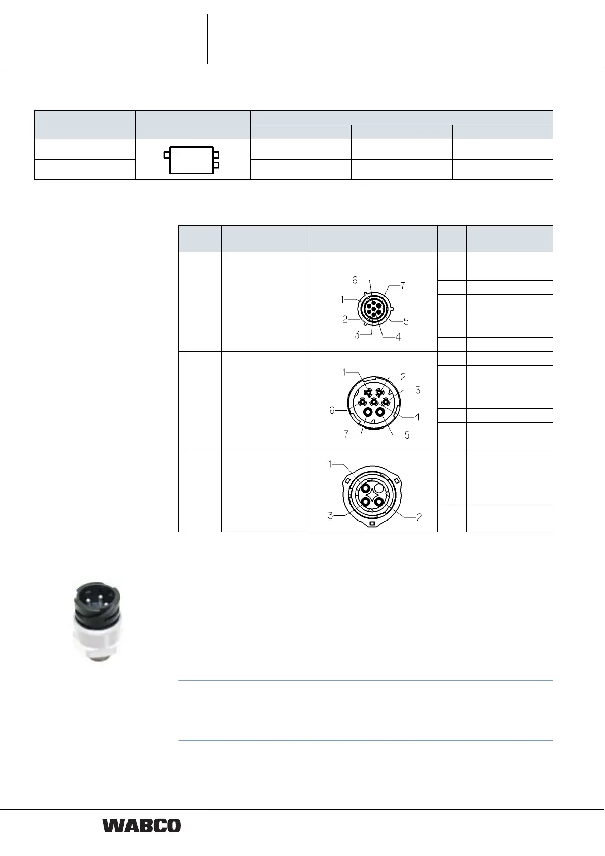
WABCO number Housing symbol
Electrical connections (DIN bayonet)
Z - Power IN X1 - Power OUT1 Y - Pressure sensor
446 122 051 0 Socket Connector Socket
446 122 053 0 Connector Connector Socket
Pos.
Connection
designation
Connector PIN Application
Z Power IN 1 CAN Low
2 CAN High
3 WALA
4 GND (Term. 15)
5 GND
6 Pin 15
7 Pin 30
X1 / X2 Power OUT1 /
Power OUT2
1 CAN Low
2 CAN High
3 WALA
4 GND (Term. 15)
5 GND
6 Pin 15
7 Pin 30
Y Pressure sensor
1 Sensor SUPPLY
2 GND
3 Sensor IN
 Loading...