9
3
CAN Router
CAN Repeater
Components
3.1.1 Variants of the CAN router
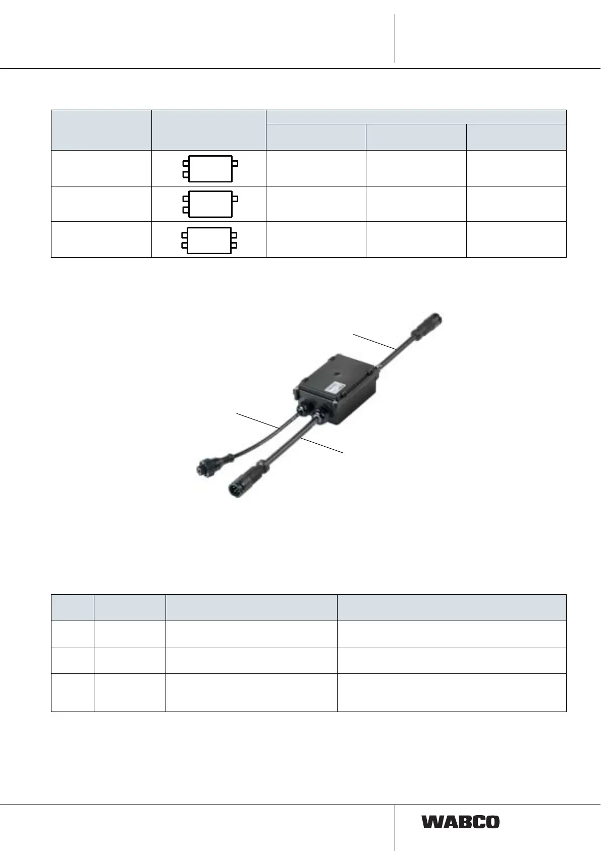
3.2 CAN Repeater
The CAN repeater (446 122 051 0 / 053 0) mainly consists of the ECU with two
connecting cables (Z, X1) with 7-pin DIN bayonet plug-in connectors and the
connecting cable (Y) for the external nominal pressure sensor.
Electrical connections To identify the connections, the connection designations are shown on a sticker on
the housing cover and on small tags on the connectors.
WABCO number Housing symbol
Electrical connections (DIN bayonet)
Z - Power IN
X1 - Power OUT1
X2 - Power OUT2
Y - Pressure sensor
446 122 050 0 Socket Connector –
446 122 052 0 Connector Connector –
446 122 054 0 Connector Connector Socket
Pos.
Connection
designation
Function Connection cable
Z Power IN Power supply (ISO 7638) from tow
vehicle
449 133 … 0 / 449 135 … 0 (for semitrailer)
449 231 … 0 / 449 233 … 0 (for drawbar trailer)
X1 Power OUT1 Connection T-EBS modulator 449 347 … 0 (for T-EBS E)
449 333 … 0 (for T-EBS D)
Y Pressure
sensor
Connection of the external nominal
pressure sensor (only as of T-EBS
E1)
449 425 … 0
 Loading...