8
3
CAN Router
CAN Repeater
Components
3 Components
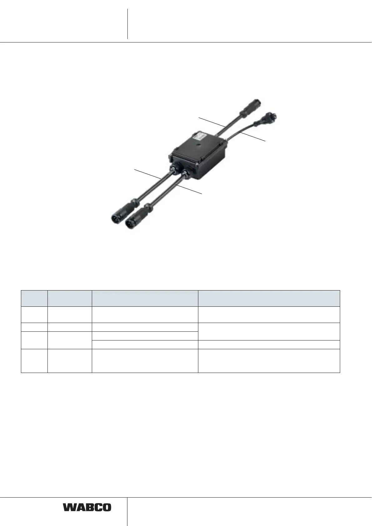
3.1 CAN Router
The CAN router (446 122 050 0 / 052 0) mainly consists of the ECU and three
connecting cables (Z, X1, X2) with 7-pin DIN bayonet plugs. With version 446 122
054 0, there is another connecting cable (Y) to an external nominal pressure sensor.
Electrical connections To identify the connections, the connection designations are shown on a sticker on
the housing cover and on small tags on the connectors.
Pos.
Connection
designation
Function Connection cable
Z Power IN Power supply (ISO 7638) from tow
vehicle
449 133 … 0 / 449 135 … 0 (for semitrailer)
449 231 … 0 / 449 233 … 0 (for drawbar trailer)
X1 Power OUT1 Connection T-EBS modulator
449 347 … 0 (for T-EBS E)
449 333 … 0 (for T-EBS D)
X2 Power OUT2 Connection T-EBS modulator
Connection for next trailer 449 135 … 0
Y Pressure
sensor
Connection of the external nominal
pressure sensor (only as of T-EBS
E1)
449 425 … 0
 Loading...