8.0 REPLACEMENT OF PARTS
VM
2
TOR.VM.--.M.A.0518.EN Issue: A
05.18
25
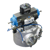
7) Insert the ange in the bushing seat. Use two long screws
positioned 180 degrees from each other as centring pins,
so that the holes of the ange match the holes of the body,
prevent the ange from rotating.
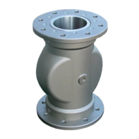
8) Using a press (or the forks of a forklift) to abut the bushing-
ange unit to the body. Tighten the ange to the body by
means of the holes, and be reminded to replace the two long
screws used as pins with suitable screws to fasten the ange.
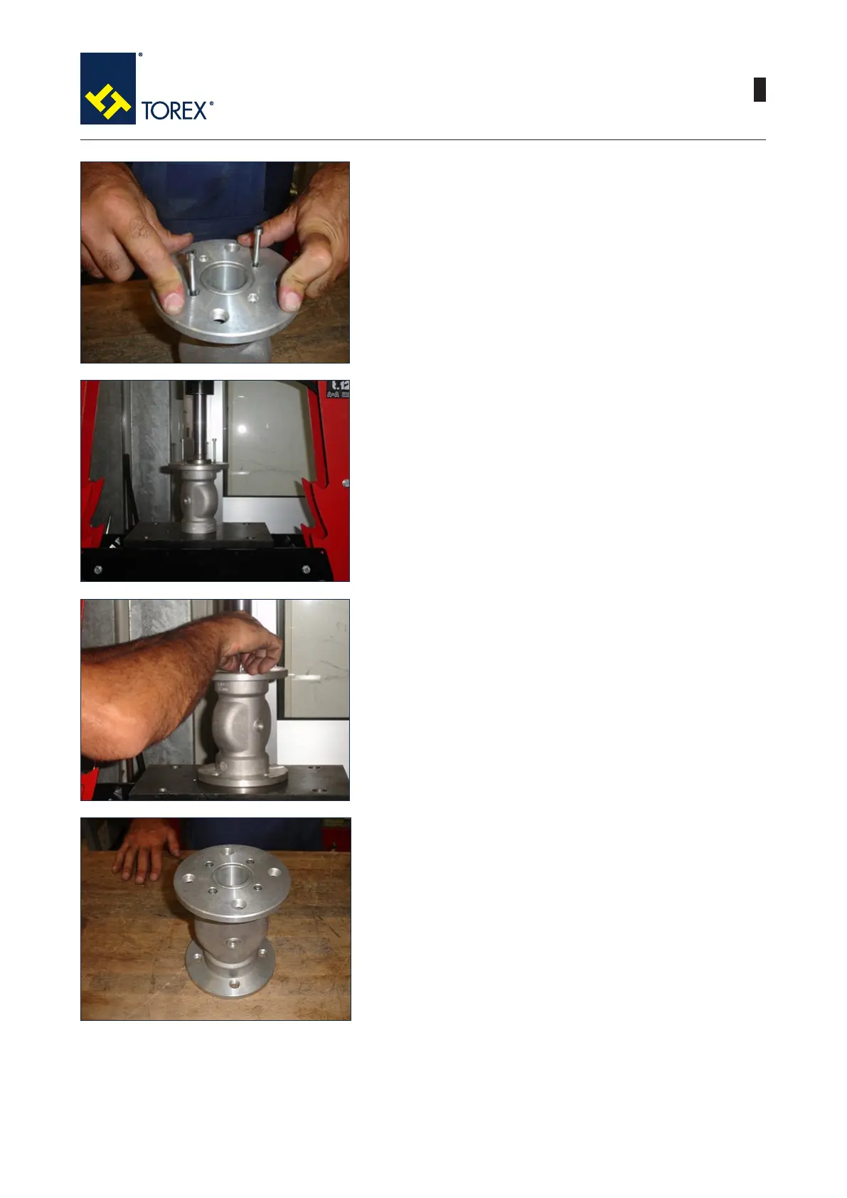
9) Repeat the steps 5.6.7.8. for the opposite side of the valve.
10) Now the valve is completely assembled.
 Loading...