EasyManuals Logo
Home>Webasto>Controller>UniControl

Webasto UniControl Installation Instructions

Webasto UniControl
13 pages
To Next Page IconTo Next Page
To Previous Page IconTo Previous Page
Page #11 background imageLoading...
Page #11 background image
UniControl 11
9 Electrical Connections
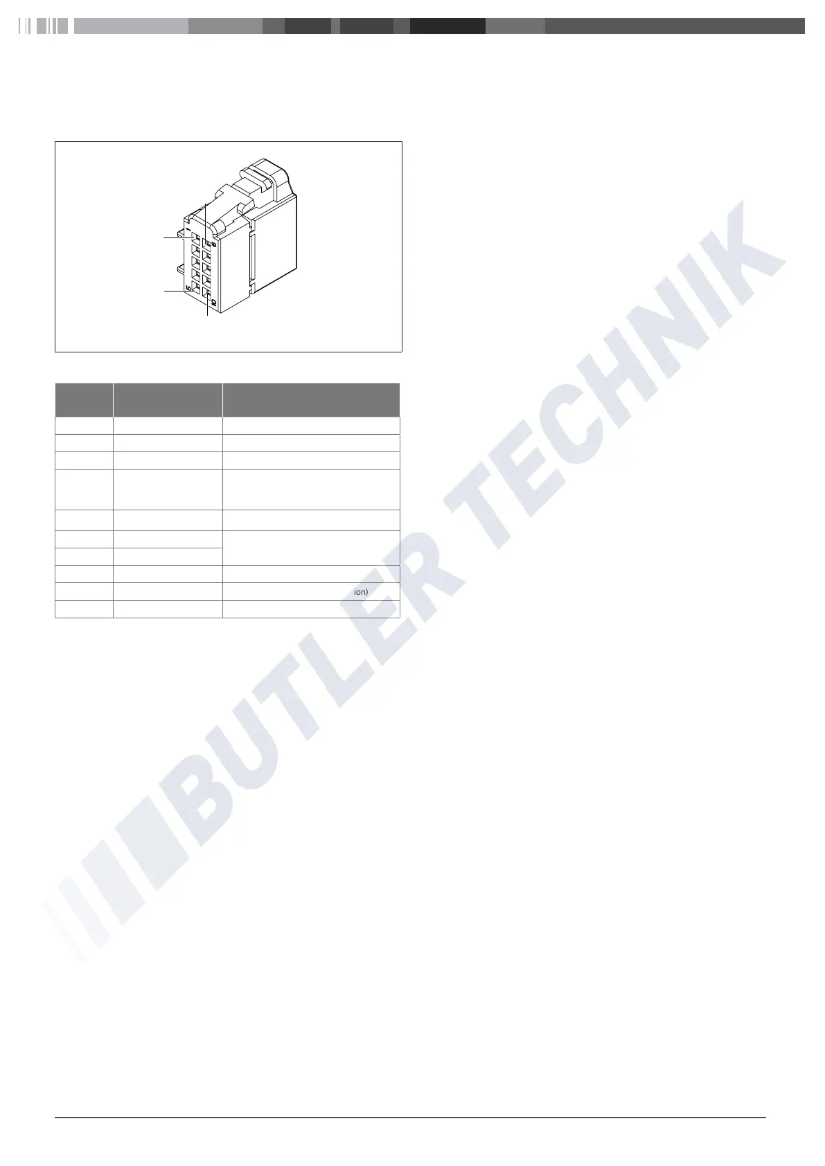
Connector designation
1
5
6
10
Fig. 17: UniControl wiring harness connector
Termi-
nal
Description Remarks
1 Connector 31 (Vehicle) Battery -
2 W-bus Data link for heater
3 Switch output Analog switch-on signal for the heater
4 Switch input
Button, analog
Switches on by a temporary chassis
ground (terminal 31).
5 Connector 30 (Vehicle) Battery +
6 Setpoint sensor -
Temperature set point (only for analog air
heaters)
7 Setpoint sensor +
8 - -
9 Connector 58 (Vehicle) Illumination (dashboard illumination)
10 Connector 15 (Vehicle) Ignition positive
www.butlertechnik.com

Other manuals for Webasto UniControl

Questions and Answers:

Question and Answer IconNeed help?

Do you have a question about the Webasto UniControl and is the answer not in the manual?

Webasto UniControl Specifications

General IconGeneral
BrandWebasto
ModelUniControl
CategoryController
LanguageEnglish

Related product manuals