
Do you have a question about the weBoost 460066 and is the answer not in the manual?
| Model Number | 460066 |
|---|---|
| Type | Cell Phone Signal Booster |
| Power Source | AC |
| Power | 12V |
| Compatible Carriers | AT&T, T-Mobile, Verizon, Sprint, US Cellular |
| Frequency Bands | 700MHz, 800MHz, 1700MHz, 1900MHz, 2100MHz |
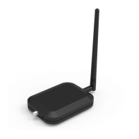
Includes the main booster unit and its accompanying internal antenna.
Refers to the coaxial cables used for connecting the booster system components.
Components for the external antenna and its mounting hardware.
The adapter used to provide electrical power to the signal booster.
Attach the Booster Antenna to the Home Studio/Home Studio Lite Booster and place in room where stronger cell signal is needed.
Pole mounting is preferred as it will be easier to adjust to the direction of the cell tower. Use U-Bolts to attach the Antenna to a pole or exhaust pipe on roof.
Connect the white RG-6 Cable to Outside Antenna and route and connect cable to Home Studio/Home Studio Lite Booster. All connections should be finger tightened only.
Plug the Power Supply into wall outlet then connect into end of Booster. We strongly recommend using a power strip with surge protection.
Indicates the Home Studio or Home Studio Lite Booster is functioning properly and there are no issues with installation.
Band has shutoff due to a feedback loop condition called oscillation. This is a built-in safety feature.
Indicates the Booster is operating at a reduced gain to prevent oscillation (feedback). This is a built-in safety feature.
Band has reduced gain due to overload from a nearby cell tower. This is a built-in safety feature.
Band has shutoff due to overload from nearby cell tower. Outside Antenna must be adjusted.
If the Signal Amplifier's light is off, verify your Power Supply has power.
Addresses issues related to solid red or blinking green/red light indicators, often caused by connection or distance problems.
Addresses issues related to solid yellow or blinking green/yellow light indicators, typically requiring antenna adjustment.
Verify connections, use only provided power supply, and maintain minimum antenna distance from persons.
Register the device with your wireless provider and operate it only in a fixed location for in-building use.
Provides links and information for registering your signal booster with various wireless carriers.
Details maximum permissible antenna gain (dBi) for the Home Studio model across various frequency bands.
Details maximum permissible antenna gain (dBi) for the Home Studio Lite model across various frequency bands.
Specifies coaxial type, length, and antenna type for the inside antenna.
Specifies coaxial type, length, and antenna type for the outside antenna.
Details model, FCC ID, connectors, impedance, frequency, power output, noise figure, isolation, and power requirements.
Details model, FCC ID, connectors, impedance, frequency, power output, noise figure, isolation, and power requirements.
Covers defects in workmanship and materials for two years; repair or replacement options are available.
States that weBoost assumes no responsibility for losses arising from the use of provided information or patent infringements.