WAS.handling Electro Documentation 24
3.5 Connection Diagram for control cables
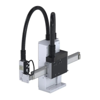
3.5.1 CAN-Bus – without I/O-Module
The drive controls will be connected to each other with the preconfigured cable 563-200000200. Terminal
resistors are inside the plugs.
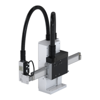
3.5.2 CAN-Bus – with one I/O-Module
Both drive controls and the I/O-Module will be connected together via cable 563-200000202. In the plug at the
end of the line, a terminal resistor is integrated. Onto the I/O-Module, the bridge ‘Term’ has to be wired.
3.5.3 CAN-Bus – two of I/O-Modules
At the version with two I/O-Modules and two drive controls, the cable 563-200000204 has to be used. The
Wiring is similar as with one I/O-Module, but the bridge “TERM” is necessary only at the end of the line.
Clamp Function
Pin 1 Bridge
Pin 2 Bridge
Pin 3 n.c.
Pin 4 n.c.
Pin 5 n.c.
Pin 6 n.c.
Pin 7 CAN – H
Pin 8 CAN – GND
Pin 9 CAN – L
Pin 10 Shield (black)
Pin 11 GND
Pin 12 +24V Supply
CAN-Adresses:
Slot PLC: “0A“
Plug-In Module AC110: “1B“
CAN-Adresses:
Slot PLC: “0A“
Plug-In Module AC110: “1B“
I/O – Module 1: “CC“
I/O – Module 2: “CD“
 Loading...