29 WAS.handling Electro Documentation
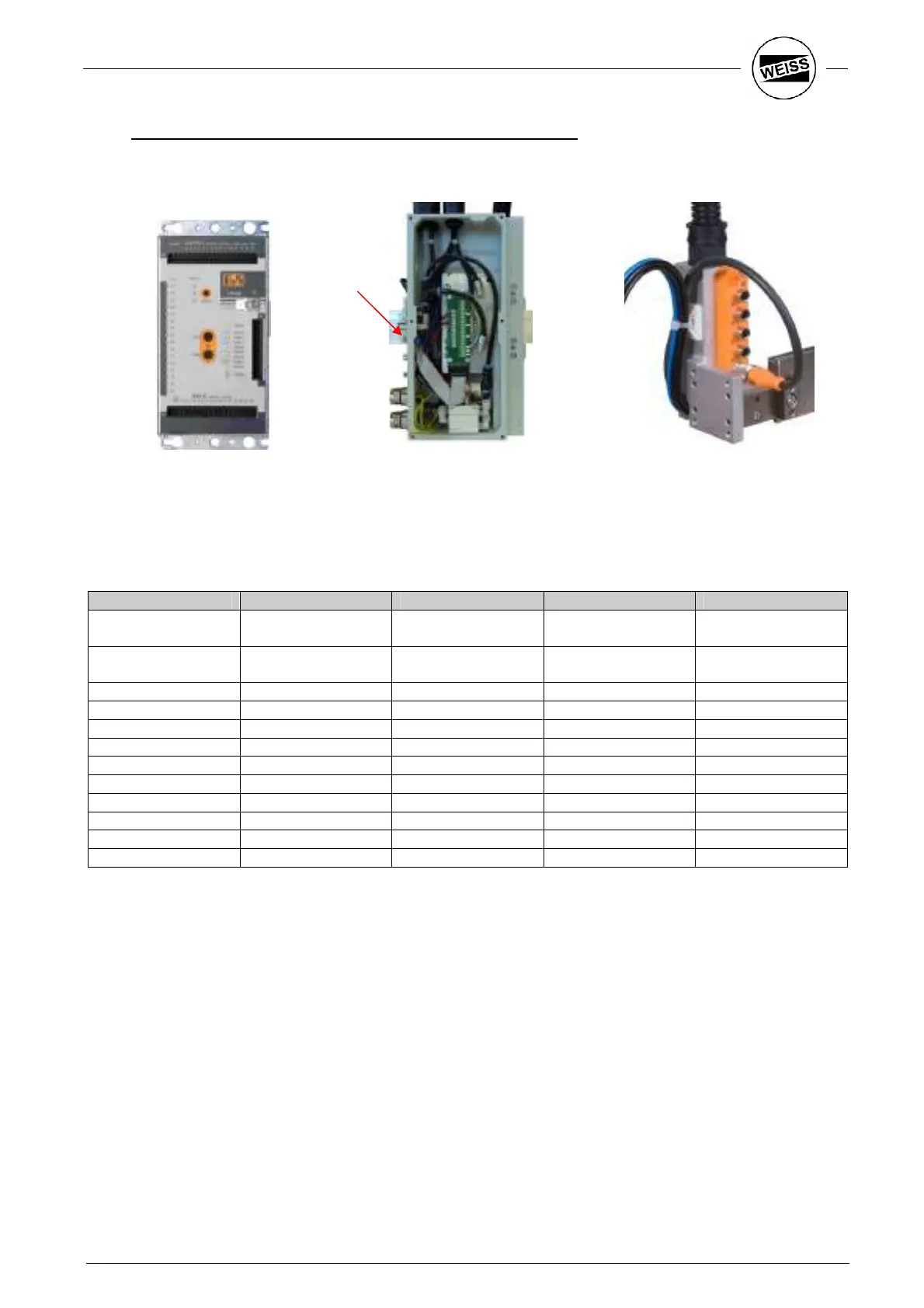
3.7.4 Connection of control lines HP140 – X40 + Tool-Connector
I/O – Module (CX408) Terminal block HP140 Tool-Connector SBS4
As described before, the use of In- and Outputs is freely configurable. For connecting I/O’s with the HP140,
there is a preconfigured cable delivered.
If pneumatic valves and Tool-Connector are requested, the wiring is as follows:
Sensor / Actor Color SBS4 Terminal block Pin X40 color of wire
+ 24V brown (+) 1, 9
black +
white
24V GND blue (-) 2, 10
violet +
brown
Valve 1 A1 13 white/green
Valve 2 A2 6 rose
A3 14 brown/green
A4 7 blue
A5 15 rot
Sensor 1 white E1 3 green
Sensor 2 green E2 11 green/red
Sensor 3 yellow E3 4 yellow
Sensor 4 gray E4 12 red/blue
E5 5 gray
X40
 Loading...