Important: Turn off the gas and electricity supplies before
replacing any components.
15.1 After the replacement of any components always check for
gas soundness where relevant and carryout functional checks as
described in Section 12-Commissioning.
Any O-ring or gasket that appears damaged must be replaced.
Complete gasket and O-ring packs are available for gas and
water connections on the appliance.
15.2 Component Access
Refer to Section 14, Inspection and Servicing for access to
components.
15.3 Draining the Appliance
Primary System: Turn off the heating flow and return valves at
the appliance. Refer to Fig 16.
Open the drain tap. Refer to Fig 17. Close the drain tap when the
flow from the appliance has stopped.
DHW Circuit: Turn off the mains cold water supply at the
appliance. Refer to Fig 16.
Open a hot tap below the level of the appliance to drain the
domestic hot water from the appliance.
Important: A small quantity of water will remain in some
components even after the appliance has been drained.
Protect any electrical components when removing items from
the water circuits.
15.4 Component Replacement
Refer to Fig 41 and 45 for an indication of the location of the
various components.
Replace any components removed from the appliance in the
reverse order using new gaskets/O-rings/sealant/heat transfer
paste where necessary. Always check that any electrical
connections are correctly made and that all screws are tight.
Remove casing and cover panels and lower the facia, as
necessary, to gain access to the components. Refer to Section 14,
Inspection and Servicing.
15.4.1 Gas Valve
Do not remove the inner casing.
Unscrew the union connections above and below the gas valve
and remove the assembly. Disconnect/unplug the electrical
connections from the valve. Use new gaskets when replacing the
valve. Refer to Fig 45.
Set the Gas Valve:
Connect a pressure gauge to the burner pressure test point on
the valve. Refer to Fig 36.
15. Replacement Of Parts
22
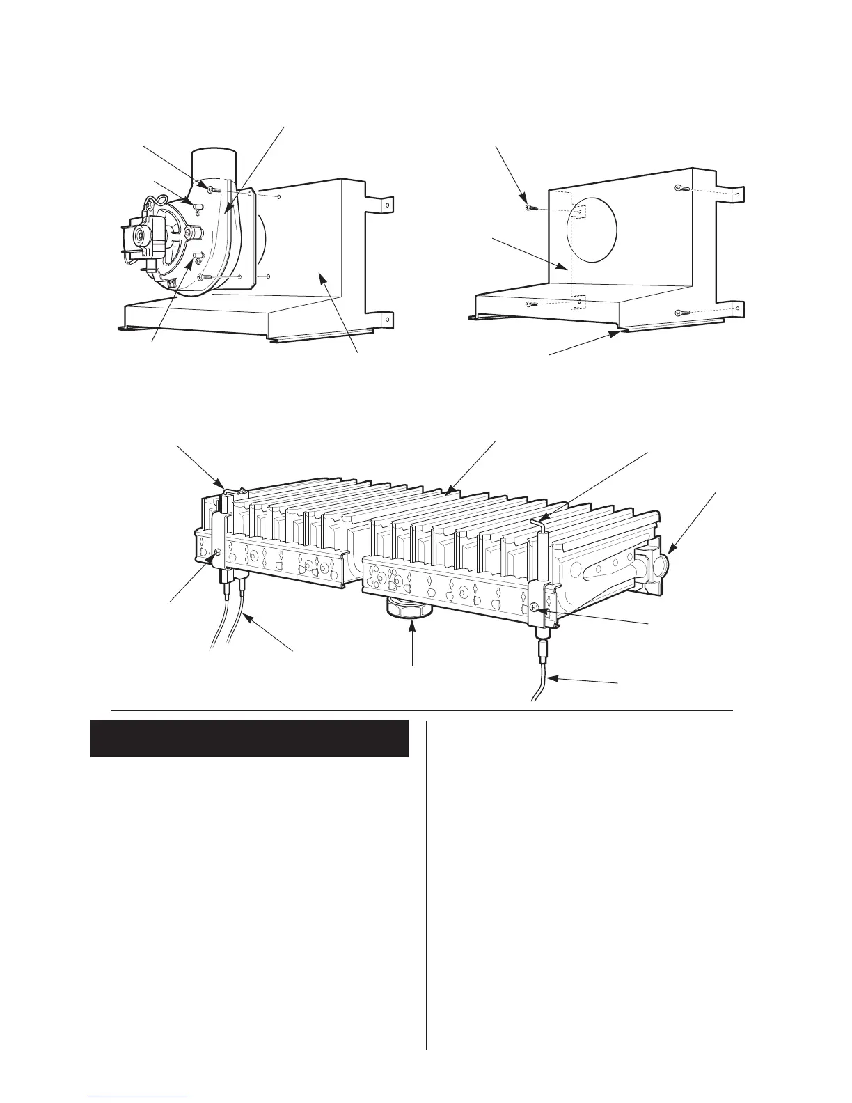
Fig.42. Fan assembly
Fig.43. Flue hood
Fig.44. Burner assembly
Fan assembly
Fan assembly fixing
screws
Air flow sensing
tube
Air flow sensing
tube (red)
Flue hood
Flue hood fixing screws
Flue hood
Flue hood/Heat exchanger guide
Spark electrode assembly
Fixing screw
Spark electrode leads
Burner connection
union
Fixing screw
Flame sense
electrode lead
Burner manifold
Flame sense
electrode
Burner blade
assembly
NOTE: Front and rear cross-
lighting strips are not shown
 Loading...