The flue system must be installed following the requirements of
BS5440: 1.
Standard flue kit length is 330 - 725mm (as measured from the
centre of the flue turret) with extension kits for flues up to
2975mm measured from the central line of the flue turret.
The terminal must not cause an obstruction or the combustion
products a nuisance.
Under some conditions the terminal might steam and positions
where this might be a nuisance should be avoided. Refer to Fig 7
If the terminal is less than 2m above a surface to which people
have access then a guard must be fitted. The guard must be
evenly spaced about the terminal and fixed with plated screws.
A Type K2 guard is available from Tower Flue Components, Vale
Rise, Tonbridge, TN9 1TB.
6.1 The appliance does not require a separate vent for
combustion air.
6.2 The appliance can be fitted in a cupboard with no vents for
cooling but the minimum clearances must be increased to those
given below (note the clearances at the front are for a removable
panel e.g. a door).
6.3 If the appliance is to be fitted in a cupboard or compartments
with less clearance than those above (minimum clearances given
in Section 4. Siting The Appliance) then permanent vents for
cooling are required. One at high level and one at low level, either
direct to outside air or to a room. Both vents must pass to the
same room or be on the same wall to the outside air.
6.4 The minimum free areas required are:
6. Air Supply5. Flue terminal positions
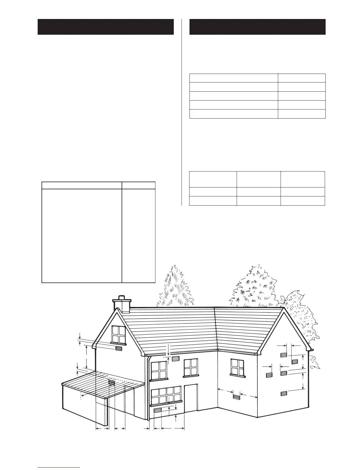
7
Fig. 7. Siting of the flue terminal.
TERMINAL POSITION MIN. DISTANCE
A– Directly below an openable window or
other opening e.g. air brick. 300 mm
B– Below gutters, soil pipes or drain pipes. 75 mm
C– Below eaves. 200 mm
D– Below balconies or car port roof. 200 mm
E– From vertical drain pipes and soil pipes. 75 mm
F– From internal or external corners. 300 mm
G– Above ground, roof or balcony level. 300 mm
H– From a surface facing a terminal. 600 mm
I– From a terminal facing a terminal 1200 mm
J– From an opening in a car port (e.g. door
window) into dwelling. 1200 mm
K– Vertically from a terminal on the same
wall. 1500 mm
L– Horizontally from a terminal on the same
wall. 300 mm
M– From door, window or air vent . 300 mm
Above the Turret 20mm
In front 250mm
Below 200mm
Right-hand side 75mm
Left-hand side 75mm
POSITION OF AIR FROM AIR DIRECT
AIR VENTS THE ROOM FROM OUTSIDE
HIGH LEVEL 315cm
2
158cm
2
LOW LEVEL 315cm
2
158cm
2
 Loading...