EasyManua.ls Logo

Worcester C1 User Manual

Worcester C1
56 pages
To Next Page IconTo Next Page
To Previous Page IconTo Previous Page
Page #46 background image
6
Your installer will
have provided adequate
space around the appliance
for safety and servicing. Do
not restrict this space by
the addition of cupboards,
shelves etc. close to the
appliance.
Minimum clearances in millimetres.
NOTE: If the appliance is to be enclosed after the
installation then the instructions given in Section 6, Air
Supply, of the Installation Book MUST be followed.
ROOM THERMOSTAT
A room thermostat may be fitted for control of the central heating
temperature. It will be located in one room of the home. The method
of setting a room thermostat varies with the type and manufacture.
Refer to the instructions supplied with the room thermostat.
THERMOSTATIC RADIATOR VALVES
If thermostatic radiator valves are to be fitted to the system then
they must conform to the requirements of BS2767:1972. It is advisable
to leave one valve permanently set at maximum to prevent the boiler
short cycling.
SHOWERS, BIDETS, TAPS AND MIXING
VALVES
Standard hot and cold taps and mixing valves used with the
appliance must be suitable for operating at mains pressure.
Thermostatically controlled shower valves will guard against the flow
of water at too high a temperature.
If using a pressure equalising valve, set the Domestic Hot Water
temperature control knob to the ‘MAX’ position.
Hot and cold mains fed water can be supplied direct to an
overrim flushing bidet subject to local water company requirements.
With all mains fed systems the flow of water from the individual
taps will vary with the number of outlets operated simultaneously
and the cold water mains supply pressure to the property. Flow
balancing using ‘Ball-o-Fix’ type valves is recommended to avoid an
excessive reduction in flow to individual outlets.
For further information contact Worcester Heat Systems
Technical Helpline.
HOT AND COLD FLOW
If the flow of water demanded from both hot and cold service
outlets is dependent upon mains supply, it may not be possible in
some installations to operate all outlets simultaneously.
WATER MAINS FAILURE
It is important to note that in the event of a mains water supply
failure, no tap water will be available until the mains supply is
restored. The appliance can still be used for heating provided that the
system is of the sealed system type.
RSF
Left-hand side 10
Right-hand side 10
In Front 600
Above the casing 180
Below 200
CLEARANCES
Question and Answer IconNeed help?

Do you have a question about the Worcester C1 and is the answer not in the manual?

Worcester C1 Specifications

General IconGeneral
BrandWorcester
ModelC1
CategoryBoiler
LanguageEnglish

Summary

Appliance Output Specifications

Installation Regulations

Gas Safety Regulations

Legal requirements for gas appliance installation by competent persons.

British Standards Compliance

Adherence to relevant British Standards for installation and safety.

Introduction

General Information

Appliance output, hot water flow, and pressure ratings.

Electrical Supply Requirements

Voltage, frequency, power consumption, and fuse ratings.

Gas Supply Requirements

Natural gas type, flow rate, and pressure requirements.

Installation Considerations

Indoor installation, sealed systems, and compartment fitting rules.

Flue System Details

Flue routing options and terminal requirements.

Appliance Controls Overview

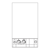
Description of controls for CH and DHW temperature adjustment.

Siting The Appliance

Flue Terminal Positions

Air Supply Requirements

No Separate Vent Required

Appliance does not need a dedicated vent for combustion air.

Cupboard Installation Clearances

Minimum clearances for fitting the appliance in a cupboard.

Cooling Ventilation Requirements

Vents needed for compartments with reduced clearances.

Minimum Free Area Requirements

Specified free areas for air vents from the room or outside.

Sealed System

System Filling and Pressure

Requirements for filling, pressurising, and venting sealed systems.

Open Vent System Suitability

Appliance is not suitable for open vent systems.

Domestic Hot Water

Gas Supply

Electrical Connections

Installing The Appliance

General Installation Notes

Suitability for sealed systems and flue installation standards.

Unpacking and Contents Check

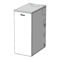
Procedures for unpacking and verifying appliance components.

Site Preparation Guidelines

Checking position, wall suitability, and required clearances.

Fixing Holes and Flue Opening

Marking and drilling points for wall mounting and flue duct.

Wall Mounting Plate and Manifold

Fitting the wall plate and connecting the manifold assembly.

Gas and Water Pipe Connections

Connecting gas and water pipes to the appliance manifold.

Boiler Installation

Air and Flue Duct Preparation

Measuring and Cutting Flue Ducts

Fitting Flue Assembly with Terminal Access

Fitting Flue Assembly without Terminal Access

Flue Bends

Vertical Adapter for Horizontal Flues

Installation Completion Checks

Commissioning The Appliance

Initial Cabinet Removal and Checks

Removing cabinet, checking supplies and connections before commissioning.

Setting Expansion Vessel Pressure

Adjusting expansion vessel charge pressure based on static head.

Setting System Pressure

Filling and pressurising the system to the correct operating pressure.

Clock/Programmer Setup

Configuring fitted clock or programmer settings.

Gas and Electricity Supply Check

Verifying gas and electricity supplies are off before pressure testing.

Checking Burner Pressure

Domestic Hot Water Operation Check

Central Heating Operation Check

System Balancing

Room Thermostat Functionality

Combined DHW and CH Operation

Commissioning Completion

Instructions To The User

User Booklet Handover

Presenting the user booklet and explaining its contents.

Safe and Efficient Operation

Guiding the user on safe and efficient appliance operation.

Cold Weather Precautions

Advising users on what to do in very cold conditions.

System Pressure Fall

Explaining actions if system pressure drops.

Importance of Regular Servicing

Highlighting the benefits of regular maintenance for efficiency and lifespan.

Competent Person Requirement

Emphasising that work must be done by qualified personnel.

Inspection And Service

Preliminary Inspection Checks

Visual checks of terminal, clearances, and joints for leaks.

Combustion Performance Test

Measuring CO2 and CO levels for correct combustion.

Replacement Of Parts

Safety Precautions Before Replacement

Turning off supplies and checking gas soundness after work.

Component Access Procedures

Referring to service section for gaining access to components.

Draining the Appliance

Steps for draining the primary and DHW circuits before component removal.

General Component Replacement Notes

Notes on using new gaskets, O-rings, and checking electrical connections.

Gas Valve Replacement

Spark Electrode Assembly Replacement

Flame Sense Electrode Replacement

Burner Replacement

Combustion Chamber Insulation Replacement

Pressure Gauge Replacement

Relief Valve Replacement

Flow Switch Replacement

Inlet Water Filter Maintenance

Control Board Replacement

Transformer Replacement

Clock/Programmer Replacement

Fan Replacement

Air Flow Detector Replacement

Primary [CH] Sensor Replacement

Overheat Thermostat Replacement

DHW Sensor Replacement

Pump Replacement

Expansion Vessel Replacement

Auto Air Vent Replacement

Primary Heat Exchanger Replacement

Air Flow Switch Replacement

Short Parts List

Operational Flow Diagrams

Fault Finding Guide

Preliminary Electrical Checks

Essential electrical checks before starting fault diagnosis.

Light Situation Indicators

Interpreting indicator light patterns for fault identification.

Fail Point A: No Power

Fail Point B: Fuse Issues

Fail Point D: Central Heating Issues

Fail Point E: Hot Water Issues

Fail Point F: Environment/Board Issues

Fail Point G: Primary Overheat

Fail Point H: Burner Lockout

Fail Point I: Sensor Faults

Fail Point J: Air Pressure Faults

Fail Point K: Gas Valve Mode Setting

Fail Point L: Water Temperature Issues

User Instructions and Customer Care Guide

General Information

Gas Safety Regulations

Legal requirements for gas appliance installation.

General Description of C1 Models

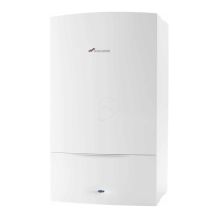
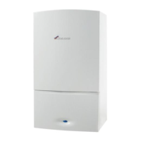
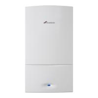
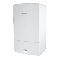
Overview of C1 appliances for DHW and central heating.

General Notes

Central Heating System Checks

Checking radiator heating and venting during initial operation.

Sealed Heating System Pressure

Maintaining and checking system pressure in sealed systems.

Clearances

Room Thermostat Installation

Information on fitting and setting a room thermostat for central heating.

Thermostatic Radiator Valves

Requirements for thermostatic radiator valves and advice on preventing short cycling.

Showers, Taps, and Mixing Valves

Suitability of water fittings for mains pressure and shower valve use.

Hot and Cold Water Flow Considerations

Managing water flow from multiple outlets simultaneously.

Water Mains Failure Impact

Effect of mains water supply failure on appliance and heating.

Use in Hard Water Areas

Ventilation of Room Sealed Appliances

Circulating Pump Settings

Frost Precautions

Annual Service Importance

Safety Warning for Gas Leaks

Cleaning the Appliance

Operation of Controls

Operating Switch Function

Turning the appliance on and off via the main switch.

Central Heating Temperature Control

Adjusting radiator water temperature and switching to hot water only mode.

Domestic Hot Water Temperature Control

Setting the domestic hot water temperature and flow adjustments.

Facia Mounted Programmer

Information on using the optional facia-mounted programmer.

Reset Button Usage

How to use the reset button for slow flashing indicator lights.

System Pressure Gauge Interpretation

Understanding the system pressure gauge readings.

Indicator Lights Explained

Lighting and Stopping the Appliance

How to Light the Appliance

Steps for turning on the appliance and setting controls.

How to Stop the Appliance

Procedures for short and long-term shutdown of the appliance.

Electricity Supply Failure Response

How the appliance behaves during and after power interruptions.

Overheat Cut-Off Thermostat Function

How the overheat thermostat triggers a lockout condition.

Ignition Lockout Procedure

Air Flow Device Lockout

Appliance Fails to Operate

Maintaining Your Appliance

Your C1 Guarantee

Guarantee Registration

Related product manuals