15.4.6 Pressure Gauge
Remove the cabinet and lower the facia panel. Refer to Fig 40.
Check that the appliance has been fully drained.
Withdraw the clip and remove the pressure-sensing head. Refer
to Fig 50.
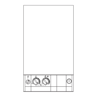
Unclip the gauge head from its mounting bracket and
remove.Refer to Fig 49
Do not omit the O-ring from the pressure capillary when fitting
the replacement gauge.
15.4.7 Relief Valve
Remove the cabinet and lower the facia.
Check that the appliance has been fully drained.
Disconnect the relief valve drainpipe. Unclip and pull-out the
valve.
Refer to Fig 51.
24
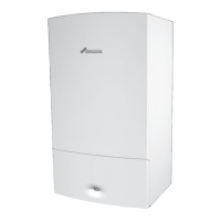
Fig.48. Combustion Chamber Insulation.
Fig.49. Pressure Gauge head
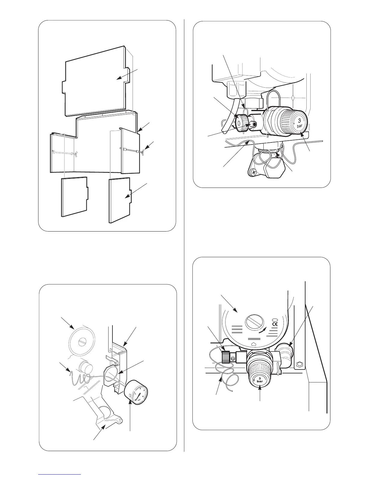
Fig.50. Pressure Gauge capillary fixing
Fig.51 . Relief valve drain connection
Pump
Relief Valve
Drain
Connection
(push fit)
Boiler
Drain
Pressure
Gauge
Capillary
Relief
Valve
Insulation
panel-front
Combustion
chamber
assembly
Fixing
screws
Insulation
panel-side
Pump
Pressure
gauge
capillary
Casing side panel
Mounting bracket
Pressure gauge head
Facia panel
Pressure gauge
capillary fixing clip
Boiler drain
ON/OFF
Boiler drain
tube
connection
(tube attached)
Pressure gauge
capillary
Relief valve
fixing clip
Relief valve
 Loading...