ALIGNMENT-4
Alignment
Main Receiver Adjustment
1st
Local Oscillator Adjustment
Set the following controls as indicated:
[IPO] button: AMP1
[ATT] button: OFF
[VRF] button: THRU
[R.FLT] button: AUTO
[AGC] button: AUTO
[RF GAIN] knob: Fully clockwise
[MODE] button: CW
Connect the RF millivoltmeter to TP1073 on the
MAIN Unit.
Press and hold in the [1(1.8)], [2(3.5)], and [3(7)]
keys, while turning the radio on, to enter the
alignment mode.
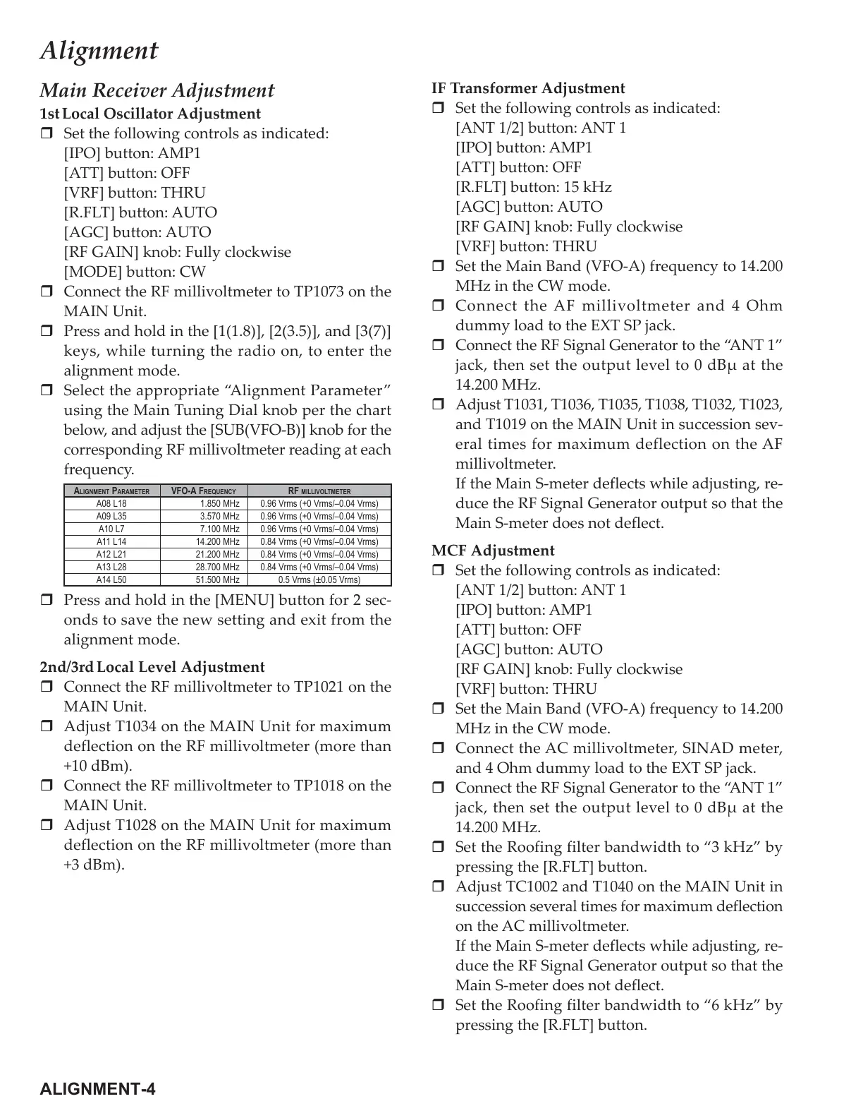
Select the appropriate “Alignment Parameter”
using the Main Tuning Dial knob per the chart
below, and adjust the [SUB(VFO-B)] knob for the
corresponding RF millivoltmeter reading at each
frequency.
Press and hold in the [MENU] button for 2 sec-
onds to save the new setting and exit from the
alignment mode.
2nd/3rd
Local Level Adjustment
Connect the RF millivoltmeter to TP1021 on the
MAIN Unit.
Adjust T1034 on the MAIN Unit for maximum
deflection on the RF millivoltmeter (more than
+10 dBm).
Connect the RF millivoltmeter to TP1018 on the
MAIN Unit.
Adjust T1028 on the MAIN Unit for maximum
deflection on the RF millivoltmeter (more than
+3 dBm).
IF Transformer Adjustment
Set the following controls as indicated:
[ANT 1/2] button: ANT 1
[IPO] button: AMP1
[ATT] button: OFF
[R.FLT] button: 15 kHz
[AGC] button: AUTO
[RF GAIN] knob: Fully clockwise
[VRF] button: THRU
Set the Main Band (VFO-A) frequency to 14.200
MHz in the CW mode.
Connect the AF millivoltmeter and 4 Ohm
dummy load to the EXT SP jack.
Connect the RF Signal Generator to the “ANT 1”
jack, then set the output level to 0 dBµ at the
14.200 MHz.
Adjust T1031, T1036, T1035, T1038, T1032, T1023,
and T1019 on the MAIN Unit in succession sev-
eral times for maximum deflection on the AF
millivoltmeter.
If the Main S-meter deflects while adjusting, re-
duce the RF Signal Generator output so that the
Main S-meter does not deflect.
MCF Adjustment
Set the following controls as indicated:
[ANT 1/2] button: ANT 1
[IPO] button: AMP1
[ATT] button: OFF
[AGC] button: AUTO
[RF GAIN] knob: Fully clockwise
[VRF] button: THRU
Set the Main Band (VFO-A) frequency to 14.200
MHz in the CW mode.
Connect the AC millivoltmeter, SINAD meter,
and 4 Ohm dummy load to the EXT SP jack.
Connect the RF Signal Generator to the “ANT 1”
jack, then set the output level to 0 dBµ at the
14.200 MHz.
Set the Roofing filter bandwidth to “3 kHz” by
pressing the [R.FLT] button.
Adjust TC1002 and T1040 on the MAIN Unit in
succession several times for maximum deflection
on the AC millivoltmeter.
If the Main S-meter deflects while adjusting, re-
duce the RF Signal Generator output so that the
Main S-meter does not deflect.
Set the Roofing filter bandwidth to “6 kHz” by
pressing the [R.FLT] button.
ALIGNMENT PARAMETER
A08 L18
A09 L35
A10 L7
A11 L14
A12 L21
A13 L28
A14 L50
VFO-A FREQUENCY
1.850 MHz
3.570 MHz
7.100 MHz
14.200 MHz
21.200 MHz
28.700 MHz
51.500 MHz
RF MILLIVOLTMETER
0.96 Vrms (+0 Vrms/–0.04 Vrms)
0.96 Vrms (+0 Vrms/–0.04 Vrms)
0.96 Vrms (+0 Vrms/–0.04 Vrms)
0.84 Vrms (+0 Vrms/–0.04 Vrms)
0.84 Vrms (+0 Vrms/–0.04 Vrms)
0.84 Vrms (+0 Vrms/–0.04 Vrms)
0.5 Vrms (±0.05 Vrms)
 Loading...