ALIGNMENT-5
Alignment
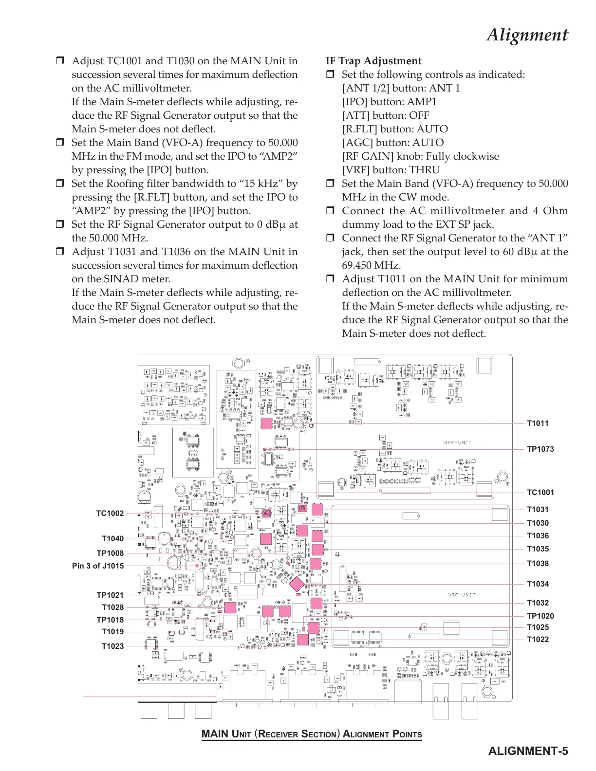
Adjust TC1001 and T1030 on the MAIN Unit in
succession several times for maximum deflection
on the AC millivoltmeter.
If the Main S-meter deflects while adjusting, re-
duce the RF Signal Generator output so that the
Main S-meter does not deflect.
Set the Main Band (VFO-A) frequency to 50.000
MHz in the FM mode, and set the IPO to “AMP2”
by pressing the [IPO] button.
Set the Roofing filter bandwidth to “15 kHz” by
pressing the [R.FLT] button, and set the IPO to
“AMP2” by pressing the [IPO] button.
Set the RF Signal Generator output to 0 dBµ at
the 50.000 MHz.
Adjust T1031 and T1036 on the MAIN Unit in
succession several times for maximum deflection
on the SINAD meter.
If the Main S-meter deflects while adjusting, re-
duce the RF Signal Generator output so that the
Main S-meter does not deflect.
IF Trap Adjustment
Set the following controls as indicated:
[ANT 1/2] button: ANT 1
[IPO] button: AMP1
[ATT] button: OFF
[R.FLT] button: AUTO
[AGC] button: AUTO
[RF GAIN] knob: Fully clockwise
[VRF] button: THRU
Set the Main Band (VFO-A) frequency to 50.000
MHz in the CW mode.
Connect the AC millivoltmeter and 4 Ohm
dummy load to the EXT SP jack.
Connect the RF Signal Generator to the “ANT 1”
jack, then set the output level to 60 dBµ at the
69.450 MHz.
Adjust T1011 on the MAIN Unit for minimum
deflection on the AC millivoltmeter.
If the Main S-meter deflects while adjusting, re-
duce the RF Signal Generator output so that the
Main S-meter does not deflect.
T1031
MAIN UNIT
(
RECEIVER SECTION
)
ALIGNMENT POINTS
T1036
T1035
T1038
T1034
T1032
T1025
T1011
TP1073
T1022
TP1020
TC1002
T1040
TP1008
TP1021
T1028
T1019
TP1018
T1030
TC1001
T1023
Pin 3 of J1015
 Loading...