CONTENTS
BLOCK DIAGRAM(ブロックダイアグラム) ....................... 3 – 5
OVERALL CONNECTOR CIRCUIT DIAGRAM
(総コネクタ接続回路図)................................................................. 6
OVERALL CIRCUIT DIAGRAM
(総回路図)
DM (001-007)............................................................... 7 – 13
AN (001-003) ............................................................. 14 – 16
PN1..................................................................................... 17
PN2..................................................................................... 18
MLN2 (001-003)......................................................... 19 – 21
MF ...................................................................................... 22
RE ....................................................................................... 23
CIRCUIT DIAGRAM
Note : See parts list for details of circuit board conponent parts.
Notation for Circuit Diagrams
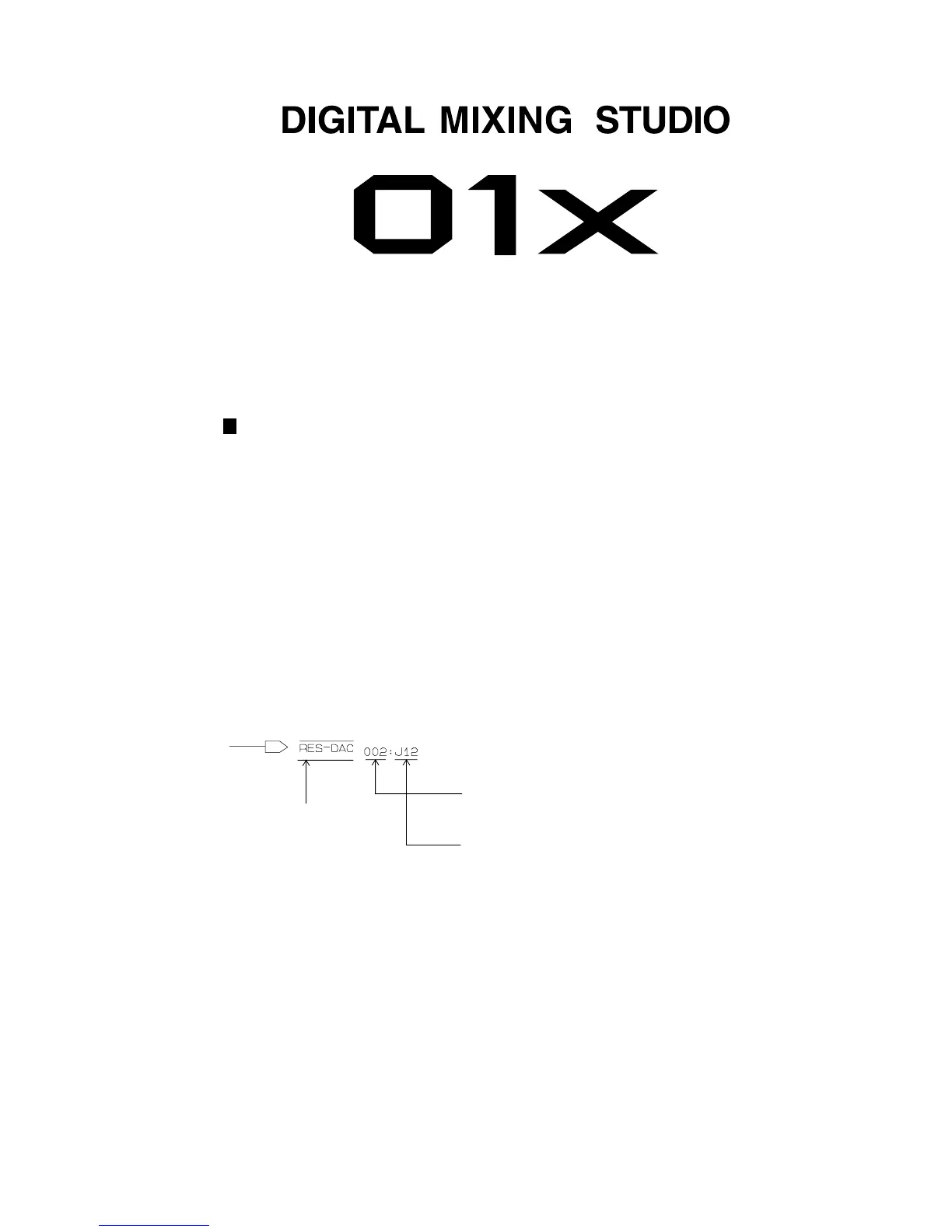
1. How to identify inter-sheet connectors(シート間コネクタの読み方について)
The 3-digit number indicates the destination page.
Signal name
This indicates the location of the counter inter-sheet connector.
(The alphabet indicates horizontal direction and the number
indicates vertical direction.)
■ WARNING
Components having special characteristics are marked
Z
and must be replaced with parts hav-
ing specification equal to those originally installed.
Z
印の部品は、安全を維持するために重要な部品です。交換する場合は、安全のために必ず指定の部品をご
使用ください。
2. Connection of connectors(コネクタの接続について)
Example: to DM-CN201 (P8)
← Page 8 shows circuit diagrams. (P8は回路図のページです。[8ページ])
(目次)
注:シートの部品詳細は、パーツリストをご参照ください。
(回路図表記上の注意)
(3桁の数字は信号の行先ページを示します。)
対応するシート間コネクタのあるロケーションを示します。
(アルファベットが水平方向、数字が垂直方向)
(信号名)
 Loading...