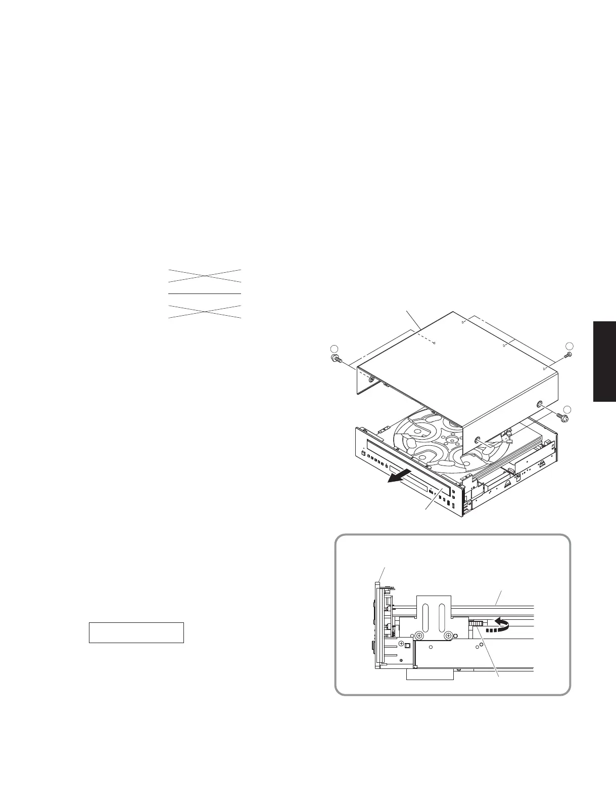
EasyManua.ls Logo

Yamaha CD-C600 Service Manual

Yamaha CD-C600
64 pages
To Next Page IconTo Next Page
To Previous Page IconTo Previous Page
Page #19 background imageLoading...
Page #19 background image
19
CD-C600
CD-C600
Top cover
Disc tray ass'y
Eject the disc tray
1
2
1
Disc tray ass'y
Gear/L0
Front panel unit
OPE:v1.09
Firmware version
Fig. 1
Required tools
Program down loader program
....................................................... FlashSta.exe
• Firmware
................................................... C5S3_xxxx.mot
C5S3_xxxx.id
RS232C cross cable “D-sub 9 pin female”
(Specifications)
After replacing the following parts with the replacement parts, update the latest firmware according to the following
procedure.
MAIN P.C.B.
Microprocessor (IC305) of MAIN P.C.B.
UPDATING FIRMWARE
Preparation and precautions
Download the firmware down loader program and
the latest firmware from the specified source to
the same folder of the PC.
Prepare the above specified RS232C cross cable.
While writing the firmware, keep the other application
software on the PC closed.
It is also recommended to keep the software on
the task tray closed as well.
Confirmation of firmware version
Before and after updating the firmware, check the
firmware version by using the factory mode menu.
Start up the factory mode of this unit, and press the
“DISPLAY” key of the remote control. The firmware
version is displayed. (See “FACTORY MODE”)
Note down the displayed firmware version.
Pin No.2 RxD Pin No.2 RxD
Pin No.3 TxD Pin No.3 TxD
Pin No.5 GND Pin No.5 GND
Pin No.7 RTS Pin No.7 RTS
Pin No.8 CTS Pin No.8 CTS
Connection
*
Turn off the power of this unit and disconnect the
power cable from the AC outlet.
1. Remove 4 screws (
) and 3 screws (
), and
remove the top cover. (Fig. 1)
2. Eject the disc tray.
a. Turn gear/L0 counter clockwise gradually and
stop before the disc tray starts to move. (Fig. 1)
b. Pull out the disc tray ass’y. (Fig. 1)

Other manuals for Yamaha CD-C600

Questions and Answers:

Yamaha CD-C600 Specifications

General IconGeneral
Frequency range10 - 20000 Hz
Signal-to-Noise Ratio (SNR)106 dB
Total Harmonic Distortion (THD)0.003 %
CD-RW playbackYes
File typeMP3, WMA
Device typeHiFi CD player
Product colorBlack
Dimensions (WxDxH)435 x 116 x 405 mm
Weight and Dimensions IconWeight and Dimensions
Weight6200 g

Summary

IMPORTANT NOTICE

TO SERVICE PERSONNEL

Critical Components Information

Information on critical components and replacement requirements.

Leakage Current Measurement

Procedure to measure leakage current for safety compliance.

CHEMICAL CONTENT NOTICE

Notice regarding chemical content and safety precautions.

Laser Safety Precautions

Safety precautions for servicing laser components.

Laser Emitting Conditions and Properties

Laser Emitting Conditions

Conditions for laser emission during operation and servicing.

Laser Diode Properties

Technical specifications of the laser diode used in the unit.

Power Supply Warning

Safety warning regarding live mains voltage on the primary side.

PREVENTION OF ELECTROSTATIC DISCHARGE

Grounding for ESD Prevention

Methods for grounding to prevent ESD damage.

FRONT PANEL Layout

REAR PANELS Configurations

REMOTE CONTROL PANEL

Caution for Moving Unit

Precautions to take when moving the unit to prevent damage.

SPECIFICATIONS

Audio Section Specifications

Technical specifications for the audio performance.

General Specifications

General specifications like power supply, consumption, and dimensions.

Dimensions and Accessories

Physical dimensions and included accessories.

INTERNAL VIEW

DISASSEMBLY PROCEDURES

Top Cover and Clamp Removal

Steps to remove the top cover and clamp assembly.

Disc Tray and Table Removal

Instructions for removing the disc tray and internal table.

Further Disassembly and Installation Steps

Front Panel Unit Removal

Procedure to remove the front panel unit.

Table Installation Precautions

Critical steps for correctly installing the table.

Component Unit Removal

CM-230B Unit Removal

Steps for removing the CM-230B unit.

PU Mechanism Unit Removal

Instructions for removing the pick-up mechanism unit.

Operation Check Procedure

Disassembly for Check

Steps for disassembling the unit for operation checks.

Test Mode Activation

How to enter test mode for fault checking.

PCB Checking and Connection Procedures

PCB Checking Procedures

Specific instructions for checking PCBs and connections.

Grounding and Cable Connection

Connecting ground points and reconnecting cables.

STANDARD OPERATION CHART

Detailed Operation Chart Steps

Operation Chart Steps

Key steps in the standard operation flowchart.

TEST MODE

Starting and Canceling Test Mode

Procedures to enter and exit the device's test mode.

Test Mode Operations

List of functions and key codes for test mode operations.

FACTORY MODE

Starting and Canceling Factory Mode

Procedures to activate and exit factory mode.

Factory Mode Operations

Key codes and functions available in factory mode.

UPDATING FIRMWARE

Required Tools and Preparation

List of tools, software, and precautions for firmware updates.

Connection and Firmware Version Check

Steps to connect and verify firmware versions.

Firmware Update Procedure

RS-232C Connection

Connecting the unit to a PC for firmware update.

Firmware Update Execution

Firmware Update Procedure

Detailed steps for performing the firmware update.

Firmware Writing and Verification

Setting Baud Rate and Erasing Memory

Steps to set baud rate and erase device memory.

Starting Firmware Writing

Initiating the firmware writing process.

Post-Firmware Update Procedures

Firmware Writing Completion and EEPROM Initialization

Verifying firmware and initializing EEPROM after update.

DISPLAY DATA and Pin Connections

Display Data and Grid Assignment

Information on display segments and their assignments.

Pin Connection Diagrams

Visual diagrams of IC pin connections.

IC Data

LC786922 IC Details

Pin assignments and functions for the LC786922 IC.

IC Pin Functions (1-40)

IC Pin Functions (41-62)

IC Pin Functions and Notes

IC Pin Functions (63-80)

Detailed pin functions from 63 through 80.

Pin Usage Notes

Important notes regarding pin usage and connections.

IC305 Microprocessor Details

Microprocessor I/O Ports and Peripherals

Overview of the microprocessor's I/O ports and peripheral functions.

Microprocessor Port Functions

Port Functions (Port 0-3)

Detailed pin functions for Ports 0 through 3.

Microprocessor Port Functions Continued

Port Functions (Port 7, PWM, UHD, RES, XT, CF)

Detailed pin functions for Ports 7, PWM, UHD, RES, XT, CF.

IC305 Pin Connections Overview

Microprocessor I/O Ports Overview

Overview of the microprocessor's I/O ports.

Peripheral Functions Summary

Summary of peripheral functions available on the microprocessor.

Microprocessor Pin Functions (1-50)

Microprocessor Pin Functions (51-80)

A/D Port Key Detection

Details on detecting key inputs via the A/D port.

IC Pin Connection Diagrams

Integrated Circuit Pinouts

Pin connection diagrams for various integrated circuits.

Component Identification: Diodes

Component Identification: Transistors

MEMO

BLOCK DIAGRAM

Analog Output and PU Mechanism

Block diagrams of analog output and PU mechanism.

Disc Tray and Control Sections

Block diagrams of disc tray and control sections.

Power Supply Circuit Diagram

Block diagram of the power supply circuit.

PRINTED CIRCUIT BOARDS: Main PCB (Side A)

PRINTED CIRCUIT BOARDS: Main PCB (Side B)

PRINTED CIRCUIT BOARDS: Operation (1-4) Side A

PRINTED CIRCUIT BOARDS: Operation (1-4) Side B

PRINTED CIRCUIT BOARDS: Operation (5-9) Side A

PRINTED CIRCUIT BOARDS: Operation (5-9) Side B

PRINTED CIRCUIT BOARDS: Operation (10,12-14) Side A

PRINTED CIRCUIT BOARDS: Operation (10,12-14) Side B

PRINTED CIRCUIT BOARDS: Operation (11) Side A

PRINTED CIRCUIT BOARDS: Operation (11) Side B

SCHEMATIC DIAGRAMS: Main & Operation (9)

Main Board Schematic

Schematic diagram for the main board.

Operation (9) Board Schematic

Schematic diagram for Operation board 9.

PU Mechanism & Disc Tray Schematics

Schematics for PU mechanism and disc tray.

Power Supply & Control Schematics

Schematics for power supply and control sections.

SCHEMATIC DIAGRAMS: Main 2/2 & Others

Main Board Schematic Part 2

Second part of the main schematic diagram.

DC/DC Converter & Buffer Schematics

Schematics for DC/DC converter and buffer.

Microprocessor & EEPROM Schematics

Schematics related to microprocessor and EEPROM.

Remote Control Interface Schematic

Schematic for the remote control interface.

SCHEMATIC DIAGRAMS: Operation (1-4)

Operation (1) Schematic

Schematic for Operation board 1.

Operation (2) Schematic

Schematic for Operation board 2.

Operation (3) Schematic

Schematic for Operation board 3.

Operation (4) Schematic

Schematic for Operation board 4.

SCHEMATIC DIAGRAMS: Operation (5-8)

Operation (5) Schematic

Schematic for Operation board 5.

Operation (6) Schematic

Schematic for Operation board 6.

Operation (7) Schematic

Schematic for Operation board 7.

Operation (8) Schematic

Schematic for Operation board 8.

SCHEMATIC DIAGRAMS: Operation (9)

Operation (9) Board Schematic

Schematic diagram for Operation board 9.

SCHEMATIC DIAGRAMS: Operation (10-14)

Operation (10) Schematic

Schematic for Operation board 10.

Operation (11) Schematic

Schematic for Operation board 11.

Operation (12) Schematic

Schematic for Operation board 12.

Operation (13) Schematic

Schematic for Operation board 13.

Operation (14) Schematic

Schematic for Operation board 14.

REPLACEMENT PARTS LIST

Electrical Component Parts

List of electrical components with part details.

Abbreviations Used in Parts List

Explains abbreviations used in the parts list.

Parts List: Main PCB

Parts List: Main & Operation PCBs

Parts List: Operation PCBs

Carbon Resistors List

OVERALL ASSEMBLY Diagram

Parts List: Ref No. Part No. Description

Accessories and Service Tools

List of accessories and service tools.

CM-230B UNIT Parts and Diagram

PU UNIT ASSEMBLY and Grease Diagram

REMOTE CONTROL Details

Remote Control Schematic

Circuit schematic of the remote control.

Remote Control Panel Layout

Layout and key codes for the remote control panel.

MEMO

YAMAHA Brand Information

Related product manuals