Front and Rear Panels
Owner’s Manual
17
English
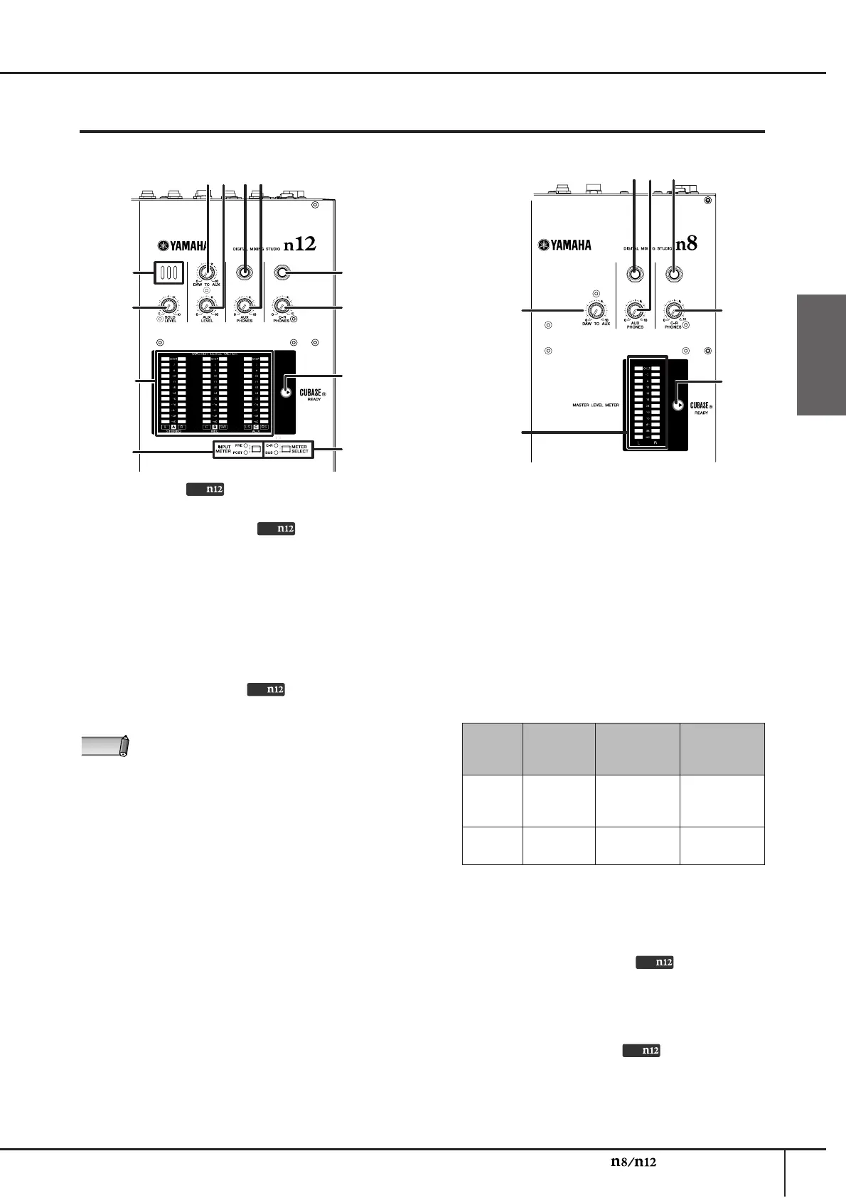
Meter section
1 Microphone
This is a built-in talkback microphone.
2 [SOLO LEVEL] control
This control adjusts the SOLO L/R bus output level. The
adjustable range is from –∞ to +6 dB. The “▼” position
corresponds to the nominal output level (0 dB).
3 [DAW TO AUX] control
This control adjusts the level of the signal routed
from the DAW AUX output (n12= DAW IN 15/16, n8=
DAW IN 11/12) to the AUX buses. The “▼” position
corresponds to the nominal output level (0 dB).
4 [AUX LEVEL] control
Adjusts the AUX OUT signal level (page 21). The “▼”
position corresponds to the nominal output level (0 dB).
5 AUX PHONES jack
This headphone connector outputs the AUX bus
signal. Use this connector to send a monitor signal
to the musicians. The output level at this jack can be
adjusted independently of the AUX OUT jacks.
6 [AUX PHONES] control
This control adjusts the output level at the AUX
PHONES jack. The “▼” position corresponds to the
nominal output level (0 dB).
7 C-R PHONES jack
This headphone jack outputs the control room
signal. The output level at this jack can be adjusted
independently from that of the C-R OUT jacks.
8 [C-R PHONES] control
This control adjusts the output level at the C-R
PHONES jack. The “▼” position corresponds to the
nominal output level (0 dB).
9 CUBASE READY indicator
This indicator lights up when the mixer is ready to be
operated with Cubase 5/Cubase 4/Cubase Studio 5/
Cubase Studio 4/Cubase Essential 5/Cubase
Essential 4/Cubase AI 5/Cubase AI 4; that is, when
the computer is connected to the n8/n12 and
Cubase is linked to the mixer correctly.
) MASTER LEVEL METER
■ n12
This meter indicates the level of the STEREO/REC/AUX
bus signals, or the output level at the C-R OUT jack. To
switch the meter view, use the [METER SELECT] switch
(
!
). Depending on the setting of the [METER SELECT]
switch, the meter indication will change as follows:
* Surround channels are indicated in parentheses.
■ n8
This meter indicates the output level at the C-R OUT
jacks.
! [METER SELECT] switch
This switch determines which signal will be indicated
via the MASTER LEVEL METER. Pressing the switch
will toggle between C-R (C-R OUT jacks) and BUS
(STEREO/REC/AUX bus).
@ [INPUT METER] switch
This switch selects the signal whose level is
indicated on the input meter (page 15) in the
Channel Control section. Pressing the switch
repeatedly toggles between PRE (pre-fader) and
POST (post-fader).
n12 n8
2
@
1
4365
8
!
7
)
9
3 8
56 7
9
)
While you are using the Monitor Remote function
(page 33), signals that pass through the DAW will be
directly routed to the AUX bus.
Only
Only
Only
NOTE
[METER
SELECT]
switch
Meter A Meter B Meter C
C-R*
C-R OUT
jacks A
(L/R)
C-R OUT
jacks B
(C/SW)
C-R OUT
jacks C
(LS/RS)
BUS
STEREO
bus
REC bus AUX bus
Only
Only
 Loading...