ABCDEFGH
1
2
3
4
5
6
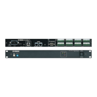
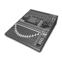
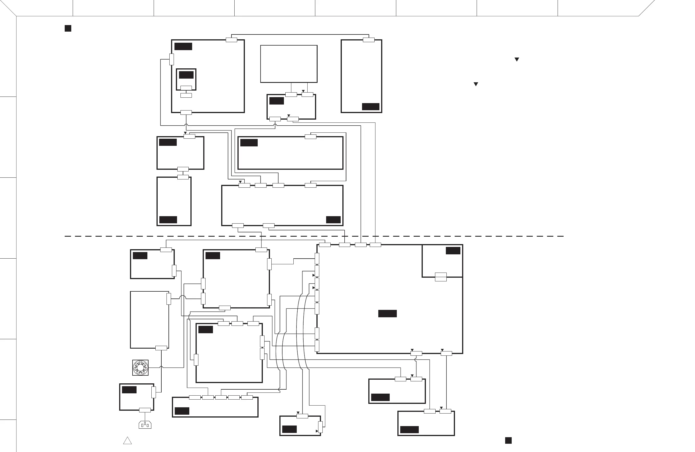
LS9-16
WIRING DIAGRAM (LS9-16)
WIRING DIAGRAM (LS9-16)28CA2-200100982212
LCD Unit
FAN
AC INLET
12P
CN101
2P
CN603
13P
CN102
2P
CN001
5P
CN002
8P
CN303
7P
CN302
3P
CN301
26P
CN601
16P
CN102
2P
CN604
12P
CN101
16P
CN401
3P
CN103
24P
CN101
24P
CN301
12P
CN102
2P
CN304
12P
CN202
20P
CN602
13P
CN201
9P
CN501
Control Panel Assembly
Bottom Assembly
Power Supply
Unit
5P
CN1
6P
CN502
6P
CN901
14P
CN503
6P
CN506
8P
CN2
16P
CN107
16P
CN108
180P
CN007
23P
CN851
23P
CN852
12P
CN902
14P
CN102
6P
CN104
7P
CN103
8P
CN504
7P
CN102
9P
CN103
26P
CN451
180P
CN101
6P
CN101
14P
CN002
14P
CN001
8P
CN903
11P
CN901
11P
CN902
OMNI OUT 1-8
34P
CN301
38P
CN401
3P
CN507
12P
CN931
14P
CN951
34P
CN501
38P
CN502
11P
CN901
8P
CN902
6P
CN603
7P
CN604
8P
CN501
INPUT 9-16
23P
CN901
16P
CN902
INPUT 1-8
23P
CN901
16P
CN902
1
Note)
注) 図中の はFFCコネクタを表し、1PinとnPin、2Pinと(n-1)Pin、
nPinと1Pinが接続されます。
なお、nPinはコネクタのPin数の最大数です。
その他のコネクタは1Pinと1Pin、nPinとnPinが接続されます。
In the drawing, the symbol shows an FFC connector by which 1Pin is
connected to nPin, 2Pin to (n-1)Pin, and nPin to 1Pin.
Where, nPin is the maximum number of pins in the connector.
Other connector connects 1Pin to 1Pin and nPin to nPin.
PNDA
PNMS
PNIN
STIN1
STIN2
ACIN
FD
ENC
INV
PHN
CPU
JK
DCA
DA
DSP
DCD
HAAD2
HAAD2
 Loading...