7-17
Outboard Rigging Guide - 2001
25HP REMOTE CONTROL ATTACHMENT KIT – 2 CYL. (6L2-48501-11-00)
REF
NO PART NUMBER DESCRIPTION QTY.
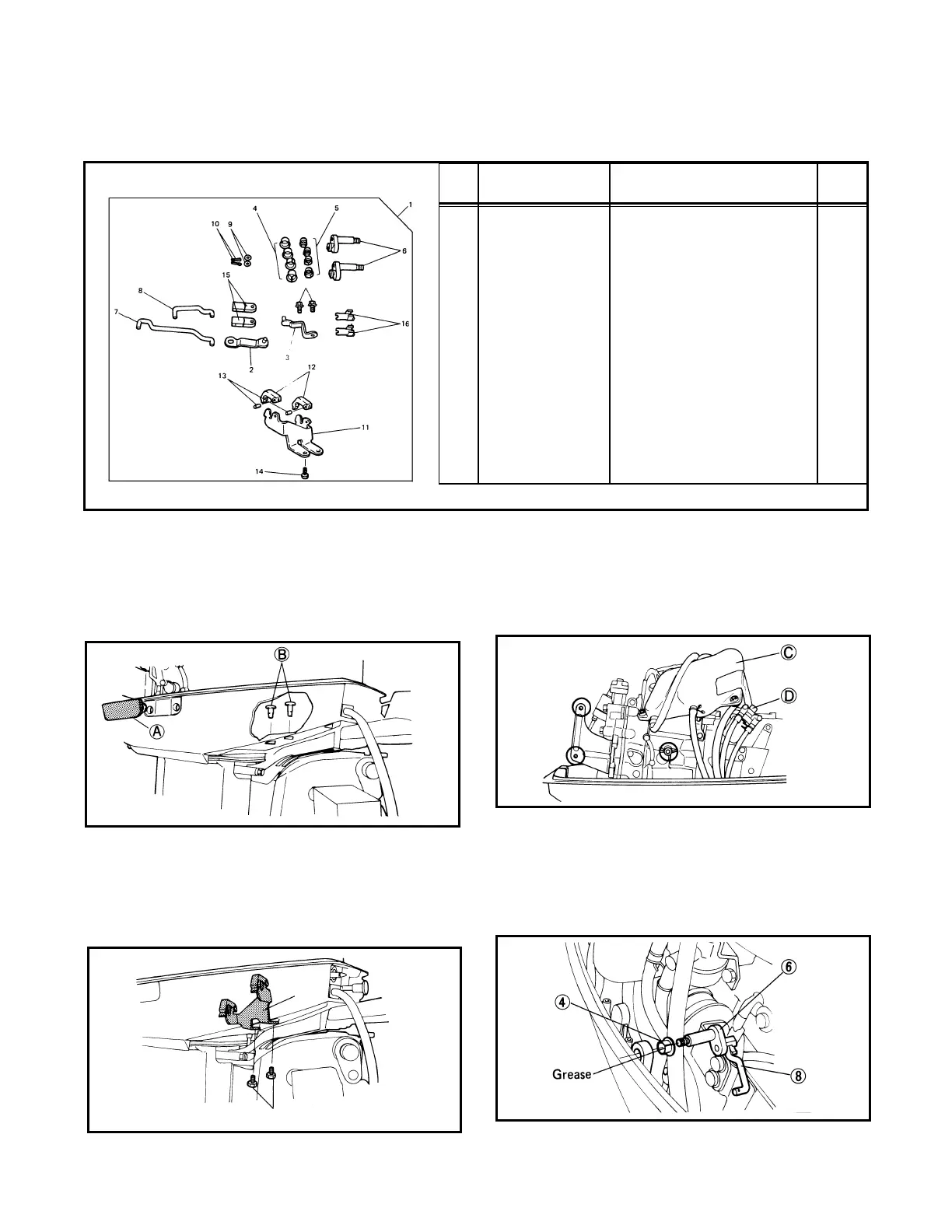
1 Remote Control Attach. Kit 1
2 6L2-48544-01-00 Shift Control Lever 1
3 6L2-48534-01-00 Throttle Control Lever 1
4 90386-10009-00 Bushing 4
5 95780-08300-00 Flange Nut 4
6 6L2-42154-01-00 Control Joint 2
7 6L2-42191-01-00 Rod 1 1
8 6L2-42192-20-00 Rod 2 1
9 90202-05088-00 Plate Washer 2
10 91490-20010-00 Cotter Pin 2
11 6L2-48531-00-00 Remote Control Bracket 1 1
12 682-48538-50-00 Cable Clamp 1 2
13 91690-30012-00 Spring Pin 2
14 90105-06M23-00 Washer-Based Bolt 2
15 6G8-26363-00-00 Cable End 2
16 6G8-26364-00-00 Lock Plate 2
• Component parts
Installation
1. Remove the grommet and plugs from the bot-
tom cowling.
A Grommet
B Plug
2. Install remote control bracket 1 to the place
where the plugs have been removed.
1 Remote Control Bracket
2 Washer-based bolt
3. Remove the oil tank mounting bolts and the
fuel filter nut. By using adhesive tape, attach
the oil tank and fuel filter nearby where they
will not impede servicing work.
C Oil Tank D Fuel Filter
4. Insert rod 2 into the hole in the throttle joint
control, fit the bushing, and install rod 2 on
the bottom link.
4 Bushing 8 Rod 2
6 Joint, control
NOTE: When fitting rod 2 to the shift rod link,
shift into Reverse and fully open the throttle.
11
22
 Loading...