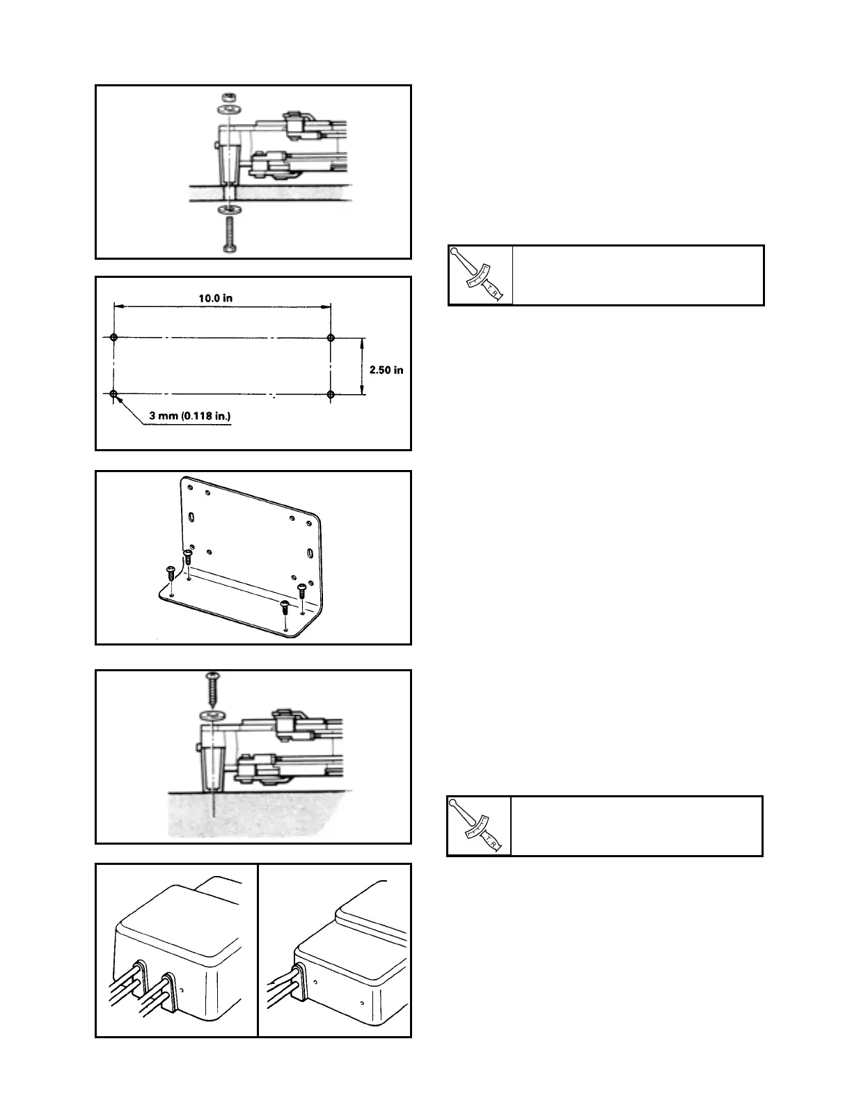
FASTENING THE JUNCTION UNIT AND THE
ACTUATOR TO THE CABIN FLOOR
1. Fastening the units using bolts
1) Bore holes, each 8.5mm (0.335 in.) in
diameter, in the cabin floor using a tem-
plate.
2) Tighten the hexagon headed bolts.
1-A Using an optional mounting bracket
1) Select a place for installation which is
recommended location.
2) Bore holes, each 3mm (0.118 in.) in
diameter, in the cabin floor referring
illustration.
3) Secure the mounting bracket to the
cabin floor with screws.
4) Secure the junction unit and actuator to
the mounting bracket with hexagon
headed bolts.
2. Fastening the units using wood screws.
1) Bore holes, each 3mm (0.0118 in.) in
diameter, in the cabin floor using a tem-
plate.
2) Tighten the wood screws.
2. INSTALLING THE COVER
(Junction unit only)
Place a rubber plug over each cable and
install the cover.
Screw:
1.5 Nm (0.15 m•kg, 1.1 ft•lb)
Screw:
5.8 Nm (0.58 m•kg, 4.1 ft•lb)
10A-33
 Loading...