model no. 054-5745-0 | contact us: 1.866.523.5218 model no. 054-5745-0 | contact us: 1.866.523.5218
31
Maintenance
Maintenance
• Disconnect chainsaw from power supply.
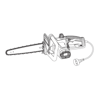
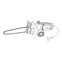
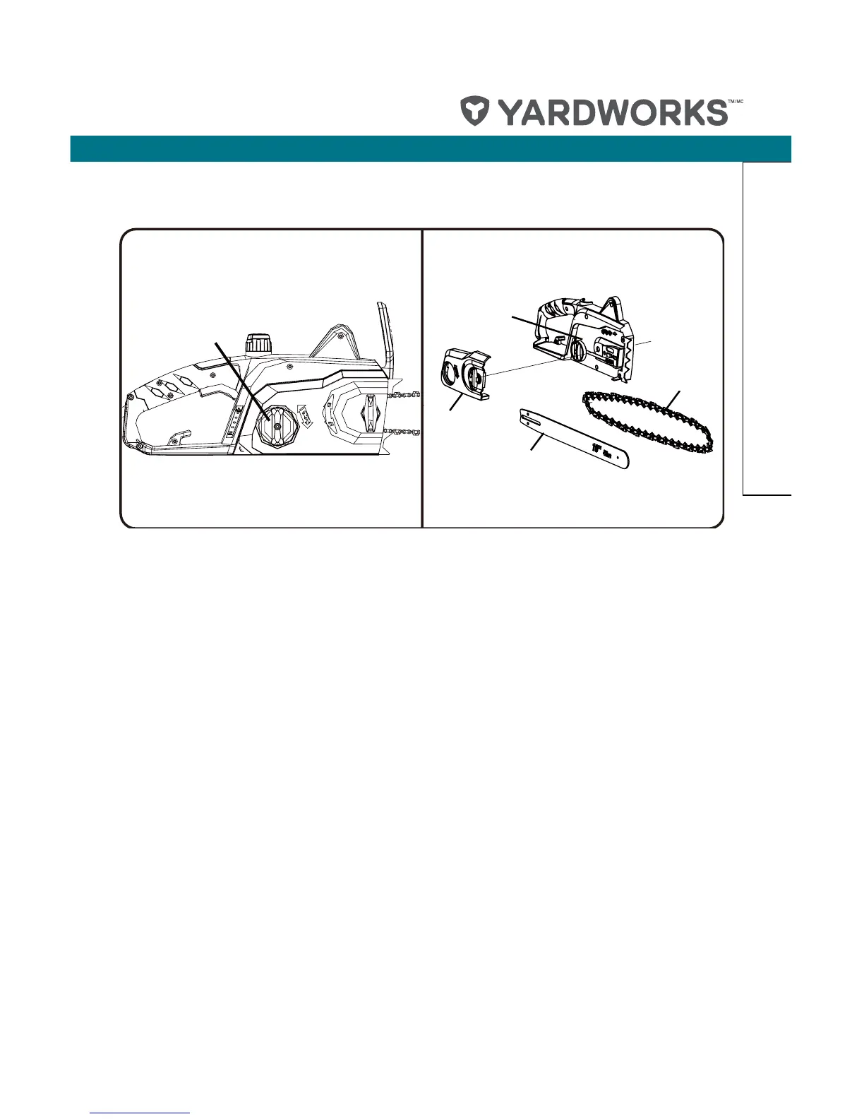
• Rotate the chain cover lock knob counter-clockwise, and remove knob (see Fig. 23).
• Remove the chain cover (see Fig. 24).
• Remove the bar and chain from the mounting surface (see Fig. 24).
• Remove the old chain from the bar (see Fig. 24).
• Lay out the new saw chain in a loop, and straighten any kinks. The cutters should face
in the direction of chain rotation. If they face backwards, turn the loop over (see Fig. 25).
• Place the chain drive links into the bar groove as shown (see Fig. 26).
NOTE: Make certain of direction of chain.
• Position the chain so there is a loop at the back of the bar (see Fig. 26).
• Hold the chain in position on the bar, and place the loop around the sprocket.
• Fit the bar flush against the mounting surface so that the bar studs are in the long slot of
the bar.
• When placing the bar on the bar studs, ensure that the adjusting pin is in the chain tension
pin hole (see Fig. 29).
• Replace the chain cover.
• Replace the chain cover lock knob. Rotate knob clockwise to tighten. The bar should still
be free to move for tension adjustment.
• Remove all slack from the chain by turning the chain tensioning knob clockwise until the
chain seats snugly against the bar with the drive links in the bar groove.
• Lift the tip of the guide bar up to check for sag (see Fig. 27).
Fig. 24Fig. 23
CHAIN
TENSIONING
KNOB
MOUNTING
SURFACE
BAR
CHAIN
COVER
CHAIN
Chain tensioning
knob
Mounting
surface
Chain cover
Bar
Chain
 Loading...