5 Transmission Interface
21
5.4 Application Layer Specifications
The data format for the application layer conforms to the MECHATROLINK-II link com-
mand specifications. The SI-T has the following main commands and sub-commands.
The main commands are used in both the 17-byte and 32-byte data transmissions for
MECHATROLINK-II and with MECHATROLINK-I. The sub-commands can be used only
when the 32-byte data transmission has been selected by means of pin 2 on DIP switch S1. If
a conflict occurs between a request for a main command and a request for a sub-command,
the request for the main command is processed. If either a main command or a sub-com-
mand is already being processed, the command being processed is given priority. If an
INV_CTL main command and an INV_I/O sub-command conflict, the sub-command over-
writes the main command.
For details on command formats, refer to Chapter 7 MECHATROLINK-II Commands.
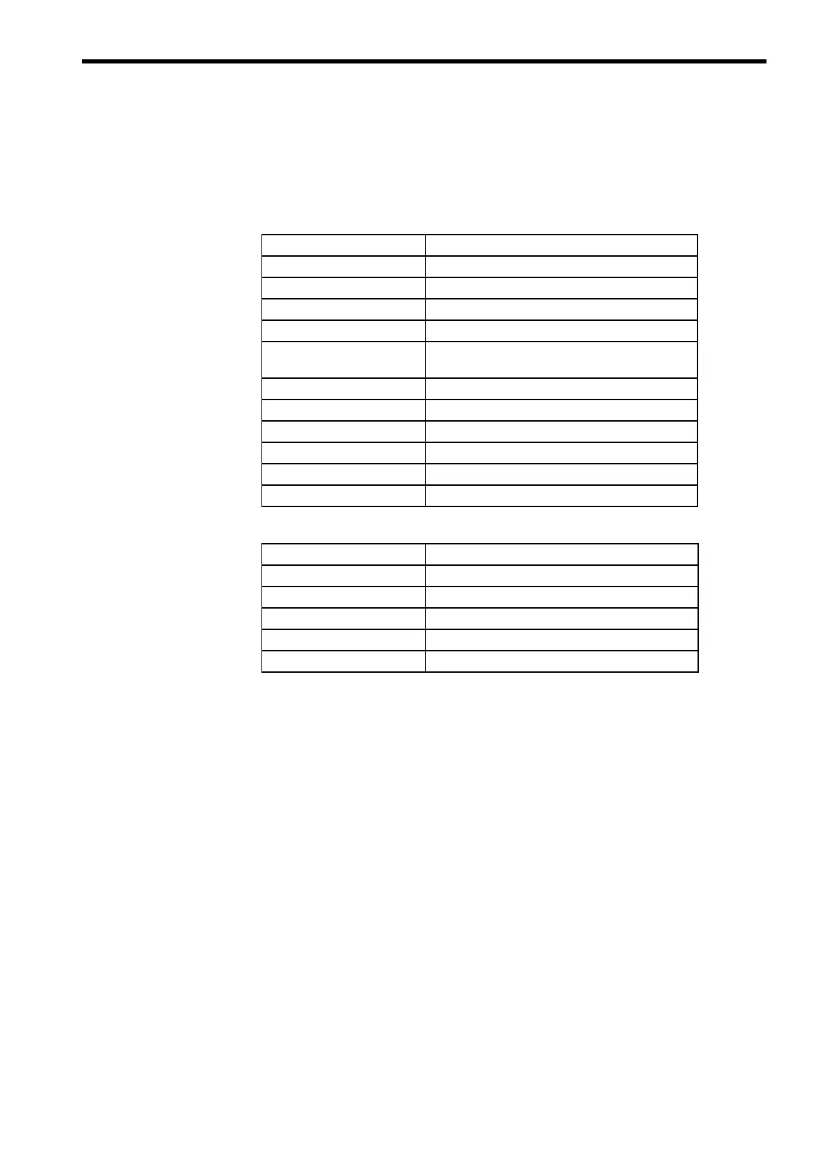
Table 1 Main Commands
Name Function
NOP No Operation
PRM_RD Reads Parameters.
PRM_WR Writes Parameters.
ID_RD Reads ID numbers.
CONFIG RAM Write ENTER_CODE and EEPROM Write
ENTER_CODE
ALM_RD Reads fault and alarm.
ALM_CLR Clears fault and alarm.
CONNECT Connect
DISCONNECT Disconnect
INV_CTL Controls Inverter Operation.
SYNC_SET Starts Synchronous Communications.
Table 2 Sub-commands
Name Function
NOP No operation
PRM_RD Reads Parameters.
PRM_WR Writes Parameters.
ALM_RD Reads fault and alarm.
INV_I/O Controls Inverter I/O.
 Loading...