2. Explosion Protection Instrumentation in Zone 2/Division 2
2-8
TI 32S01J30-01E
Example
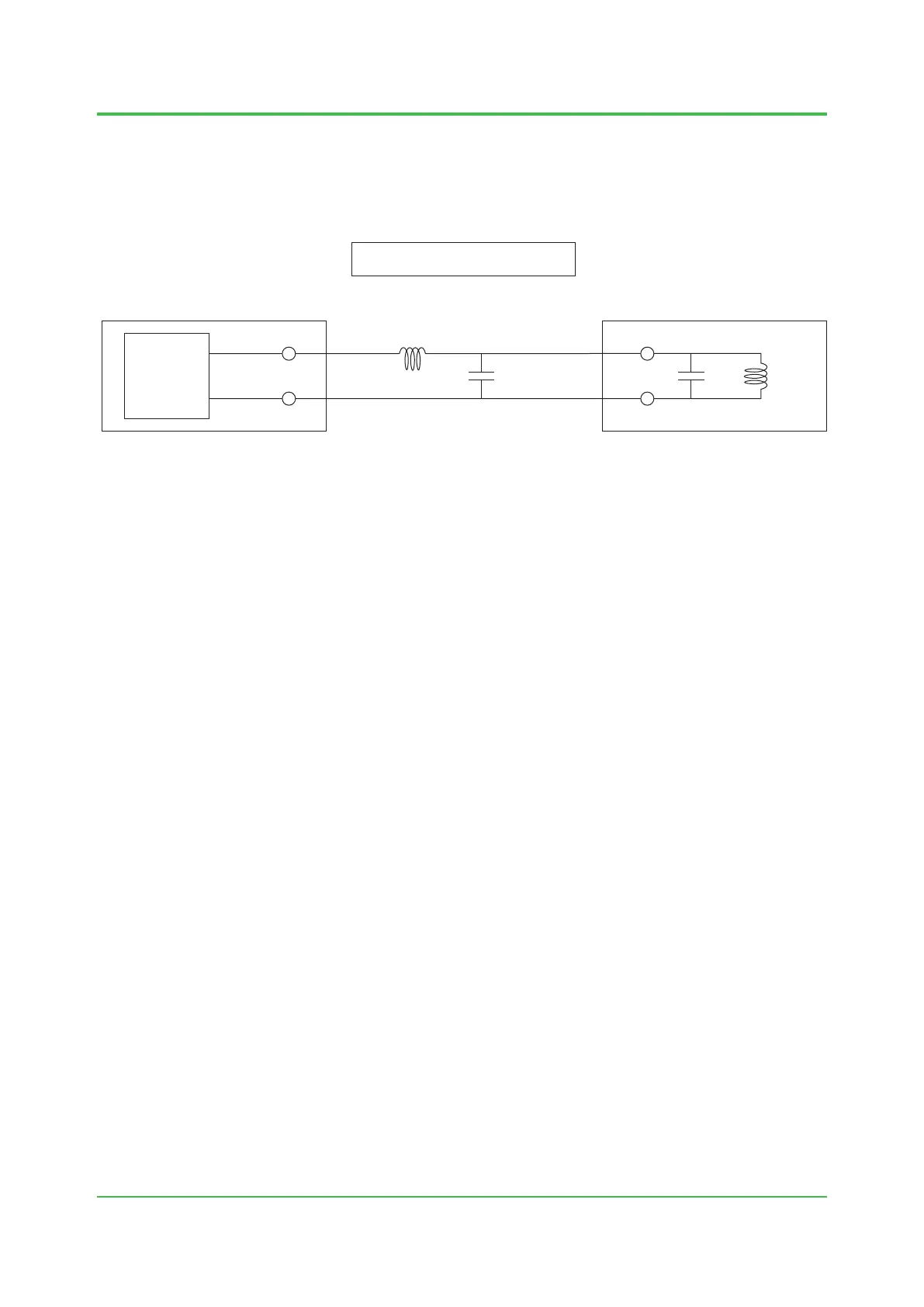
As an example, we show the case where SAI143 I/O module, a power input module and EJA,
a dierential pressure transmitter of Yokogawa Electric Corporation are connected. EJA is
connected to circuit of SAI143 via 100 m cable, and installed in Class I, Division 2 hazardous
area.
Power
Supply
Lc
Cc LiCi
Device that gives energy
(The source device)
Device that receives energy
(The load device)
Hazardous area (Class I, Division 2)
<SAI143> <Differential pressure transmitter EJA>
The defined parameters have the following values.
(Voc) = 26.4 V
(Isc) = 26 mA
(Ca) = 0.13 μF
(La) = 10 mH
and,
(Cc) = 200 pF/m 100 m = 0.0002 μF 100 = 0.02 μF
(Lc) = 0.66 μH/m 100 m = 0.00066 mH 100 = 0.066 mH
therefore,
Voc = 26.4 V < Vmax = 30 V
Isc = 26 mA < Imax = 165 mA
Ca = 0.13 μF > Ci + Cc = 0.0425 μF
La = 10 mH > Li + Lc =0.796 mH
As the results above meet the combinational conditions, we can conclude that a field wiring can be installed
in accordance with a general wiring construction.
(Vmax) = 30 V
(Imax) = 165 mA
(Ci) = 0.0225 μF
(Li) = 0.73 mH
+
-
+
-
Figure Connection of SAI143 and EJA
Dec. 3, 2021-00
 Loading...